Owner’s Manual for Portable Generator 5
Section 2 General Information and Setup
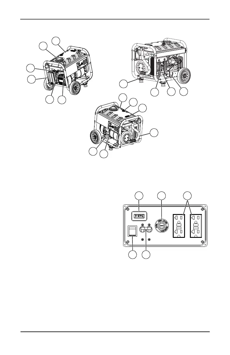
Figure 2-1. Features and Controls
Generator Components
Figure 2-2. Control Panel
7
12
6
5
16
20
21
10
15
4
14
18
11
13
17
8
1 120 Volt AC, 20 Amp, GFCI Duplex
Receptacle
2 120/240 Volt AC, 20 Amp Locking
Receptacle
3 Circuit Breakers (AC)
4 Oil Drain
5 Air Filter
6 CHOKE Knob
7 Fuel Tank
8 Grounding Lug
9 RUN/STOP Switch
10 Muffler
11 Handle
12 Gas Cap
13 Fuel Gauge
14 Oil Fill
15 Recoil Starter
16 Fuel Shut Off
17 Roll Over Valve
18 Recovery Hose
19 Hour Meter
20 Spark Arrestor
21 Carbon Canister (CARB models only)
19 2 1
9 3
 Loading...


