10 Owner’s Manual for Portable Generator
NOTE: The wheels are not intended for over-
the-road use.
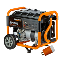
Install wheels as follows. See Figure 2-15.
1. Slide axle pin (B) through the wheel (A),
wheel bracket on frame, and flat washer
(L).
2. Insert cotter pin (F). Bend tabs (of cotter
pins) outward to lock into place.
Install frame foot as shown in Figure 2-15.
1. Place frame foot assembly (C) under
frame. Secure with M8-1.25 x 45 bolts (J)
and M8-1.25 hex flange nut (G).
.
Figure 2-15. Wheel & Frame Foot Assembly
Install handle as shown in Figure 2-16.
1. Install handle bracket (E) to frame with
M8-1.25 x 40 bolts (H).
2. Slide M8-1.25 x 55 bolts (K) through han-
dle bracket and handle (D). Install M8-1.25
hex flange nut (G).
.
Figure 2-16. Handle Assembly
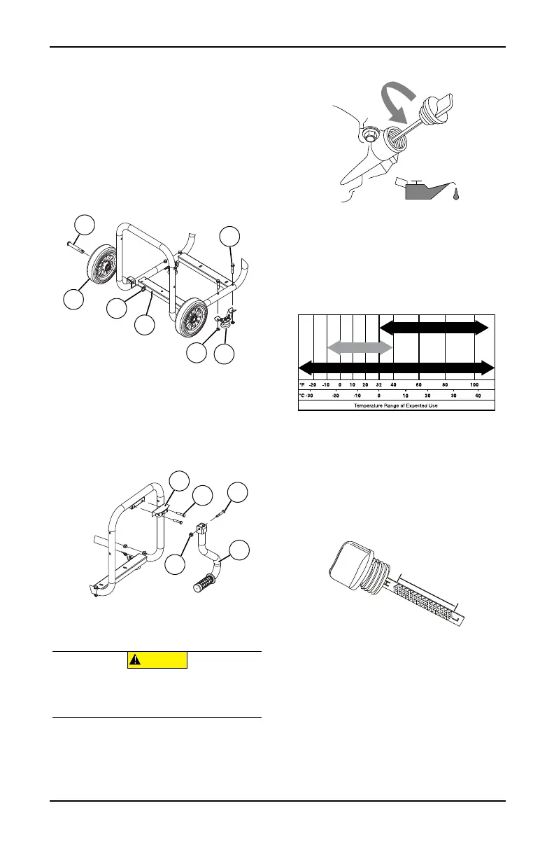
Add Engine Oil
1. Place generator on a level surface.
2. Clean area around oil fill.
3. Remove oil fill cap and wipe dipstick clean.
See Figure 2-17.
Figure 2-17. Remove Dipstick
4. Add recommended engine oil. Climate
determines proper engine oil viscosity.
See chart to select correct viscosity.
NOTE: Use petroleum based oil (supplied) for
engine break-in before using synthetic oil.
.
NOTE: Some units have more than one oil fill
location. It is only necessary to use one oil fill
point.
5. Thread dipstick into oil filler neck. Oil level
is checked with dipstick fully installed.
6. See Figure 2-18. Remove dipstick and ver-
ify oil level is within safe operating range.
Figure 2-18. Safe Operating Range
7. Install oil fill cap/dipstick and hand-tighten.
000902
(000135)
CAUTION
Engine damage. Verify proper type and quantity of
engine oil prior to starting engine. Failure to do so
could result in engine damage.
SAE 30
10W-30
Synthetic 5W-30
000399