SECTION
l0: CYUNDER
& CRANKCASE
COVER
SECTION CONTENTS
......................................PAGE
cRANKCASE..........................................._.__..._.............
t0-1
Check Crankcase ............--......................................
1 0-1
Resizing
..................................................................10-1
Cy|inderFinish........................................................1G2
Cleaninq,,,..-.---...................,,.,,,,,,,,,,,.,.,..,................
10-2
BEAR1NGs..............._.._.......................
. .........1G2
Check Mag Bearing -..-.................--..---....................
1o-2
Remove Mag
Bearing .-.--.....-..---...---........................
10-3
Innall Mag Bea ng
......... __.............__....____._..............
I0-3
Check PTO 8eadn9s
.............................-.-..-.............
104
Remove/lnstall
PTO 8eaf in9.........................__...........
t0-4
Instali PTo
oil Seal ..................................................
10-4
Check Camshaft 8earin9s...........................-............
104
Oil Seals ..................................................................
10-4
CHECK
CRANKCASE
Check crankcase
for cracks, stripped threads
or broken fins.
Check cylinder bores
fof dar.age orscoring.
l.Check
cylinder head mounting
surfacefor distortion with
a
straight edge, Figu€
10-1.
lf mounting surfaces
are distorted more
than.004'
(0.1
mm),
the crankcase mun be rcplaced.
NOTE: ff
qlinder
borcs arc within
srycification
and show
no
signs
of
scoaing ot other damage.
new
piston
ings
may be installed
Wviding
the
.ylinder bores
arc rc<on-
ditioned using a igid hone
with tinishing
stones,
to
rcstote the
prcpet
(oss
hakh
angle in the
.ylinder botet
The
proper
cylinder cross hakh
ensurcs
Noper
lubicatjon
ahd
piston
nng
hrcak in.
Refer to
'Cylinder
Finish
(C
ross Hatch)"
below for
correct
pro-
cedure for
installing cross hatch.
TOP
BOTTOIV
Figurc 10-3. Measute
at Six PoinB
RESZING:
Note: Ovefsize kits
are NOT available.
DO NOT borc
.ylinden
CYLINDER FIN SH
(CROSS
HAICH):
Finishing nones
are used when reconditioning
a cylinder
bore. Thefinishing
stones will
produce
the
correct cross hatch
necessaryfor
proper
lubrication.
The cor€ct
cross hatch
angle
is approximately 45
degrees, Figure 10-4.
Figute 10-1.
Che*ing Cylindet Head Mounting Surtace
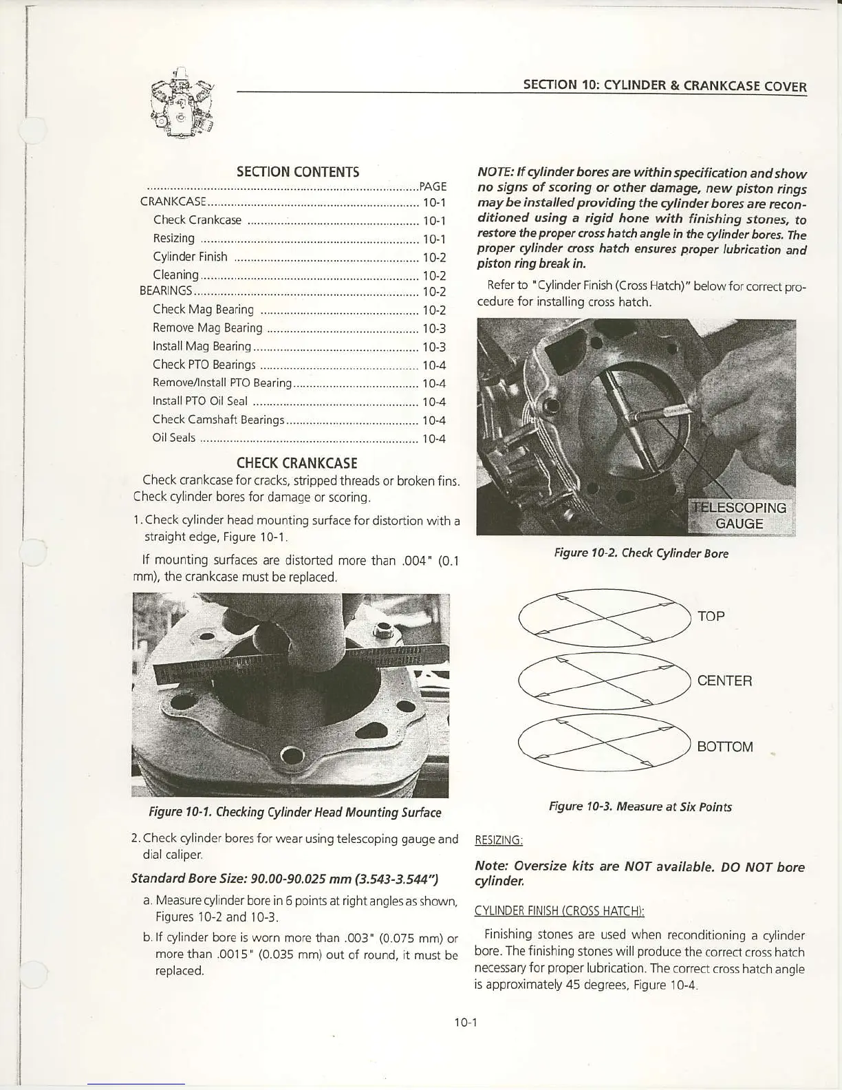
2.Check cylinder bores
for wear using telescoping
9au9e
and
dialcaliper
Standard Borc Size:
90,00-90,025 nn
(3.:A3-3.51U")
a. Measure cylinder bore in
6
points
at right:ngles
as shown,
Figures I0-2 and 10-3.
b.lf cylinder
bore is worn more than .003'
(0.075
mm) or
more
than .0015'
(0.035
mm)out
of round, ft must
be
reptaceo.
Figurc 10-Z
Che& Cylindet
Boft
101

 Loading...


