Owner’s Manual for Mobile Generator 19
General Information
Genset Controller
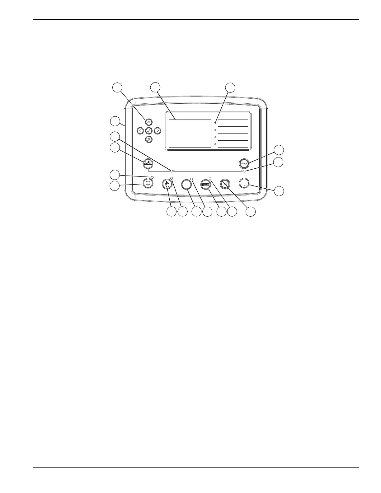
See Figure 2-8. The genset controller displays real-time
operational data, monitors functions of the generator and
engine, shuts down the unit for certain fault conditions,
displays fault data, and retains up to 250 unit
performance events.
The controller is programmable. It can automatically start
and stop the genset according to schedule, fault
condition, or load demand.
Figure 2-8. Genset Controller—Deep Sea
®
Model DSE7310 MKII
A Navigation buttons J Positive air shutoff (PAS) valve test switch LED (if
equipped)
B Screen K PAS valve test switch (if equipped)
C Indicator LED (4 locations) L MANUAL Mode LED
D Transfer to Generator button M MANUAL Mode button
E Generator Available LED N Engine STOP/RESET Mode button
F Engine START button O Engine STOP/RESET Mode LED
G Alarm Mute and Lamp Test button P Open Generator button
H AUTO Mode LED Q Open Generator LED
I AUTO Mode button R RS232 serial port (not shown—controller backside)
010417
D
F
G
I
N
P
A
B
C
M
K
H
L
O
E
Q
J
R
 Loading...