20 Mobile Link
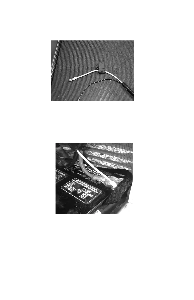
20. The power wires of the harness consist of a black negative (-)
wire and a fused yellow positive (+) wire. See Figure 3.16.
Figure 3.16 - Harness Power Wires
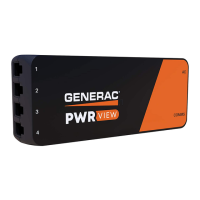
21. Loosen and remove the nuts from both the positive and nega-
tive terminal screws on the battery cables. Slide the wires over
the terminal screws and replace the nuts. Reconnect the red (+)
battery cable and tighten securely. Then, install and tighten the
black (-) cable. See Figure 3.17
Figure 3.17 - Reconnect Battery Cables.
22. Install the controller panel and sheet metal controller cover.
Install and tighten retaining fasteners.
23. Re-install the generator controller fuse.
24. Place the generator into AUTO.
25. Replace the T1 fuse into the transfer switch.
26. Turn on the main breaker in the home’s electrical panel.