Electrical Connections
Installation Manual for Generac PWRCell Inverter 13
Section 5: Electrical Connections
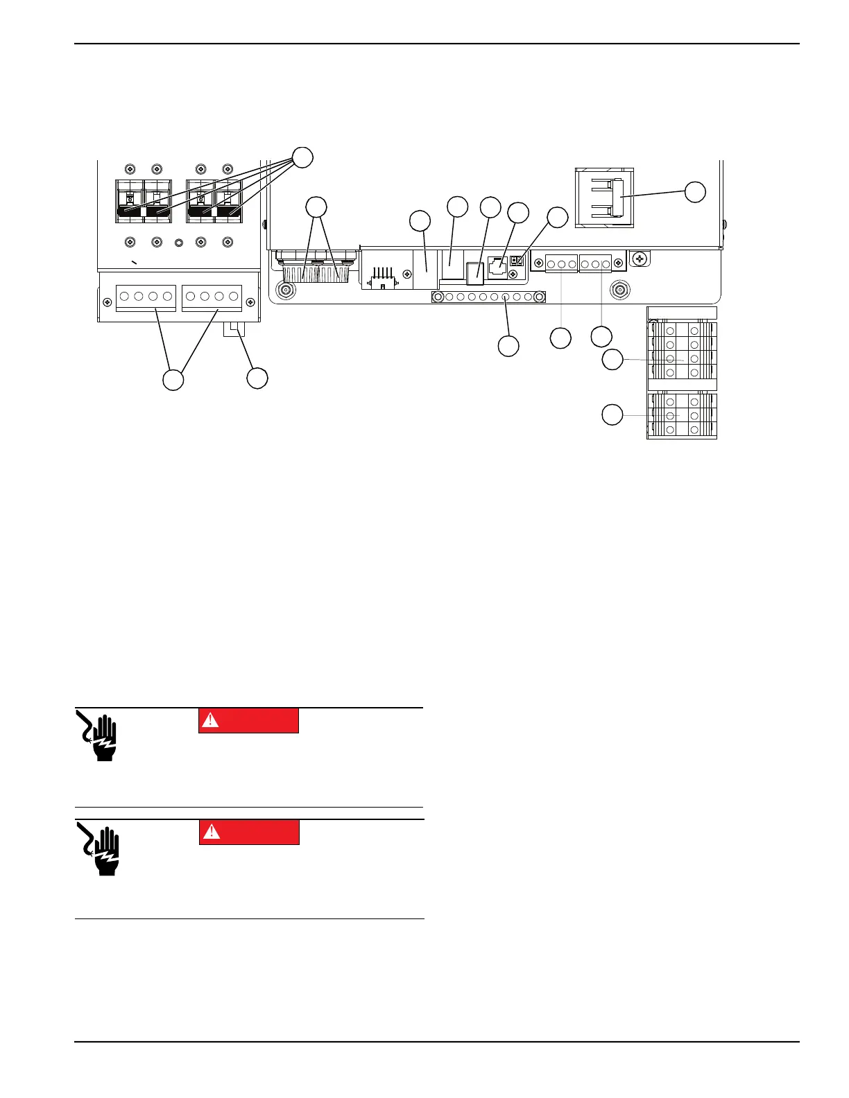
PWRcell Inverter Wiring Compartment
Figure 5-1. PWRcell Inverter Wiring Compartment
Accessing Wiring Compartment
See
Figure 5-2
.
To access the wiring compartment:
1. Initiate an inverter shutdown.
2. Open all PWRcell DC disconnects (A). Verify DC
voltage reported on LCD screen has dropped to
below 10VDC.
3. Disconnect AC Grid source from inverter. Wait for
Inverter LCD screen to turn off.
4.
Open inverter front cover by lifting the bottom to
horizontal (B) and pushing inward (C).
5. Locate wiring compartment cover (D).
6. Remove five M4X10 screws (E) and wiring
compartment cover.
7. Verify all PWRcell DC and AC terminals are below
10V, using a multi-meter.
A PWRcell DC Disconnects I STOP Terminals
B REbus Bi-directional DC Terminals J Protected Loads Disconnect
C Internet Connection K AC Grid Connection Terminals
D DC Main Fuses L Protected Loads Terminals
E Current Transformers (CTs) Accessory Ports M Grounding Bar
F Automatic Transfer Switch (ATS) Accessory Port N Gen Sense
G REbus Beacon Port O Gen Start
H Authorized Generac Personnel Only
B
C
D
M
L
K
J
I
H
G
F
E
A
009993
N
O
(000600)
DANGER
Electrocution. Initiate a system-wide shutdown and turn the
PWRcell DC Disconnect Switch OFF on all connected
batteries before performing service. Failure to do so will
result in death, serious injury, or equipment and property
damage.
(000642)
DANGER
Electrocution. Verify all system voltages are safe before
wiring. Disconnect all AC and DC sources of power before
touching terminals. Failure to ensure no dangerous
voltages are present on conductors and terminals before
wiring will result in death or serious injury.
 Loading...