Commissioning and Setup
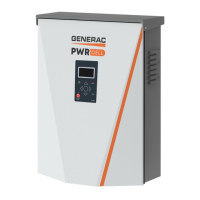
Installation Manual for Generac PWRCell Inverter 27
Configuring Inverter Settings
Configuring Systems with PWRcell Batteries
Systems with the PWRcell battery must have the EnaIs-
landing setpoint set to ON in order to island. This setpoint
is accessible through the Mod. Settings menu via the
inverter device page. See the Generac PWRcell Inverter
Owner’s Manual for information on accessing and adjust-
ing the EnaIslanding setpoint.
Verify the PWRcell inverter protected loads disconnect is
in the ON position.
Verify Battery Disconnect on the PWRcell battery is ON.
NOTE: Reference the PWRcell Battery Owner’s Manual
for advanced battery settings.
Adjusting Inverter Settings
1. See Table 6-1. Navigate to the inverter device
page using the right arrow key (next page right of
the home screen).
2. Push the center button.
3. Select Mod. Settings using the down arrow to scroll
and the center button to select.
4. Scroll through the settings using the up / down
arrow keys.
5. Use the center button to select a setting.
6. Use the up / down arrow keys to change the value
of a setting.
7. Use the center button to deselect a setting.
8. Scroll down and save all changes before exiting
the Mod. Settings menu.
9. Select Mod. Settings again to verify changes were
saved.
Table 6-1. Adjusting Inverter Settings
Setpoint Range Default Description
PLM_Channel 0 – 12 1
Channel for REbus communications. All devices in a system must use
the same channel (except REbus Beacon). Do not set equipment to
channel 0 unless performing
Multiple Inverter System Commis-
sioning Procedure
.
TargMaxImprtP -30,000 to +30,000 Watts 0
Maximum Threshold for importing power before the battery will dis-
charge in Self Supply Mode to offset.
TargMinImprtP -30,000 to +30,000 Watts 0
Minimum power import maintained by charging the battery from the grid
in Self Supply Mode.
EnaIslanding on / off on Allows system to island, providing backup power during a grid outage.
EnaExtTransfer on / off off
Turn on if an external automatic transfer switch (ATS) has been
installed to operate with the Inverter.
ExtTransVolt 50 – 200 Volts 95
Minimum voltage from the utility that must be present for the inverter to
reconnect an ATS back to the grid.
GridGoodTime 1 – 360 Seconds 15
Length of time the inverter will wait to trigger an ATS to reconnect to the
utility upon sensing grid voltage return.
Export Override on / off off
Formerly called Zero Export, this setting will inhibit the PWRcell system
from exporting power to the grid.
PLM_Disable on / off off
This setting will disable the power line communications coming from the
inverter.
CalOverride on / off off
Overrides inverter logic for automatic detection of included Generac
current transformers (CTs).
CTTurnsRatio 1,500 – 3,000 Turns 1,500 Allows a different turns ratio to be set for specific CTs.
EnaLoadShed 0,1,2 0
Select 1 if using SMM devices to shed loads. Select 2 if using the PWR-
cell ATS Controller to shed loads (with or without SMMs).
EnaACdump on / off off When available this setting will shed AC coupled PV where necessary.
GridParInvrtrs 1 – 2 1
This setting allows for two inverters to share one set of CTs. Set to 2 if
daisy chaining CTs between two inverters.
 Loading...
