Operation
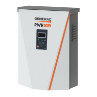
12 Owner’s Manual for Generac PWRCell Inverter
Ethernet Configuration
Ethernet Setup
For the inverter to communicate with the Generac server
an Ethernet cable with a valid Internet connection must
be plugged into the inverter Ethernet port.
• A blue Internet LED indicates the inverter has a
successful connection to the PWRview server.
• If Internet LED is not illuminated, see the Generac
PWRcell Inverter Installation Manual for
troubleshooting and connection instructions.
NOTE: It is the installer’s responsibility to make sure the
Internet connection is reliable and secure. Generac
recommends always using a hardwired connection.
Generac does not recommend or support using any
wireless or power line carrier network devices. Use these
devices at your own discretion.
Serial Number and Registration
NOTE: Registering an inverter automatically registers all
REbus system components connected to that inverter.
Every REbus-enabled device can be monitored from the
PWRview™ online monitoring system and mobile app.
To register a system for PWRview monitoring:
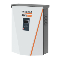
1. See Figure 3-14. Locate the serial number and
registration code on the registration decal on the
front of the inverter. This information will be
required for registration.
2. Navigate to
https://pwrfleet.generac.com or if
using a mobile device scan the registration label
QR code.
3. Follow the on-screen prompts to complete the
profile.
Table 3-1. Inverter Device Settings
Setpoint Range Default Description
PLM_Channel 0 – 12 1
Channel for REbus communications. All devices in a system must use
the same channel (except REbus Beacon). Do not set equipment to
channel 0 unless performing Multiple Inverter System Commissioning
Procedure. See installation manual for more details.
TargMaxImprtP -30,000 to +30,000 0
Maximum Threshold for importing power before the battery will discharge
in Self-Supply Mode to offset.
TargMinImprtP -30,000 to +30,000 0
Minimum power import maintained by charging the battery from the grid
in Supply Mode.
EnaIslanding on / off on Allows system to island, providing backup power during a grid outage.
EnaExtTransfer on / off off
Turn on if an external automatic transfer switch (ATS) has been installed
to operate with the Inverter.
ExtTransVolt 50 – 200 Volts 95
Minimum voltage from the utility that must be present for the inverter to
reconnect an ATS back to the grid.
GridGoodTime 1 – 360 Seconds 15
Length of time the inverter will wait to trigger an ATS to reconnect to the
utility upon sensing grid voltage return.
Export Override on / off off
Formerly called Zero Export, this setting will inhibit the PWRcell system
from exporting power to the grid.
PLM_Disable on / off off
This setting will disable the power line communications coming from the
inverter.
CalOverride on / off off
Overrides inverter logic for automatic detection of included Generac cur-
rent transformers (CTs).
CTTurnsRatio 1,500 – 3,000 Turns 1,500 Allows a different turns ratio to be set for specific CTs.
EnaLoadShed 0, 1, 2 0
Select 1 if using SMM devices to shed loads. Select 2 if using the PWR-
cell ATS Controller to shed loads (with or without SMMs).
EnaACdump on / off off When available this setting will shed AC coupled PV where necessary.
GridParInvrtrs 1 – 2 1
This setting allows for two inverters to share one set of CTs. Set to 2 if
daisy chaining CTs between two inverters.
 Loading...