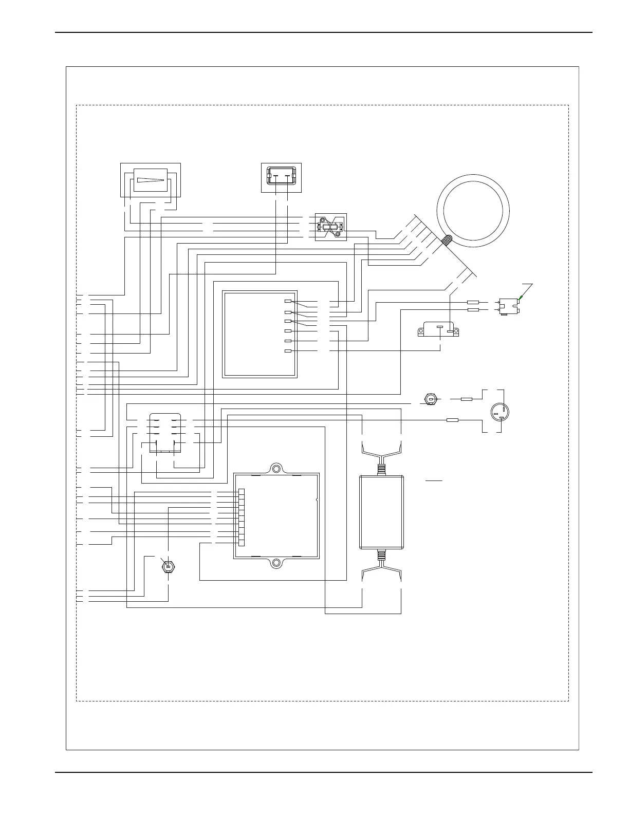
PORTABLE CONTROLLER
13
15
17
16
167
86
18
14
18A
BLK
RED
RED
RED
BLK
BLK
BLK
22S
11S
BLK
RED
RED
8
65
7
43
PBAR - POWER BAR
SCR - STARTER CONTACTOR RELAY
SC - STARTER CONTACTOR
SM - STARTER MOTOR
SP1, SP2 - SPARK PLUGS
SW1 - START-RUN-STOP SWITCH
BC
IM2 - IGNITION MODULE, CYLINDER #2
NEUT - NEUTRAL STUD
F2 - FUSE 1.5 AMP, SLO-BLO
F1 - FUSE 5 AMP
CB1 - CIRCUIT BREAKER, AUTO RESET, 5A
ICT - IDLE CONTROL TRANSFORMER
FSS - FUEL SHUT OFF SOLENOID
BCR - BATTERY CHARGE RECTIFIER
HM - HOUR METER
GND - GROUND STUD
IM1 - IGNITION MODULE, CYLINDER #1
LOP - LOW OIL PRESSURE SWITCH
BC - BATTERY CHARGER
BA - BRUSH ASSEMBLY
LEGEND
BLK
REGULATOR
VOLTAGE
0
WHT
22
33
0
0
11D
44C
44A
44
RED
RED
11
0A
15A
2
BCR
1
BLK
RED
RED
BLK
44C
11D
PBAR
162
6
0
4
162
6
0
4
22
11
22S
11S
4
22S
11S
15A
RED
2
3
1
CHARGER
BATTERY
EXTERNAL
RED
162
CB1
BA
BLK
RED
11
ICT
WHT
44A
44
HM
44
6
2
22
22S
11S
33
11
STATO R
J1
F1
13
17
1
15
15
7
4
16
167
10
9
8
18
86
15
18A
14
0
6
4
5
2
3
F2
BLK
RED
BLK
BLK
0
4
CLOSEST
TO BEARING
WIRING - DIAGRAM
10.0 PORTABLE
DRAWING #: 0H3931
REVISION:B
DATE: 1/11/11