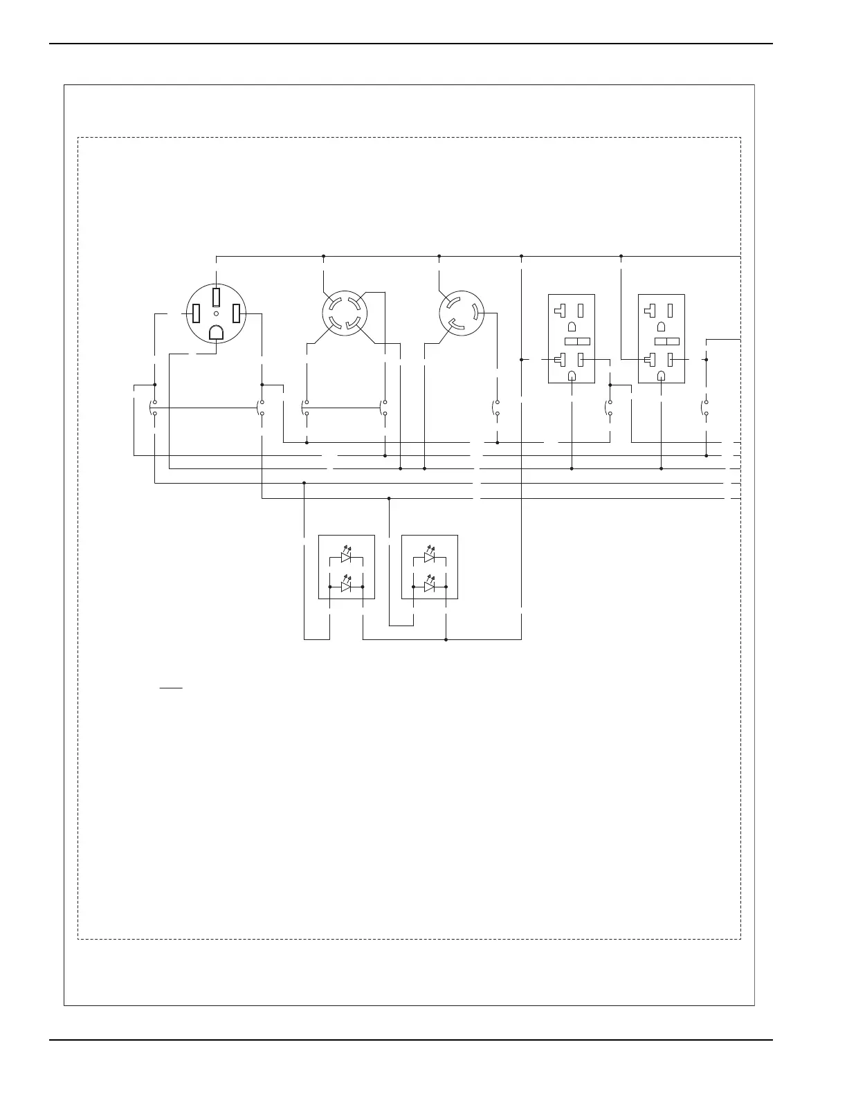
5-20R
120V/20A
GFCI
42
DPE - DISPLACED PHASE EXCITATION, 90°
SW1 - START-RUN-STOP SWITCH
SP1, SP2 - SPARK PLUGS
LOP - LOW OIL PRESSURE SWITCH
IM1 - IGNITION MODULE, CYLINDER #1
GND - GROUND STUD
SM - STARTER MOTOR
SC - STARTER CONTACTOR
HM - HOUR METER
SCR - STARTER CONTACTOR RELAY
ICT - IDLE CONTROL TRANSFORMER
NEUT - NEUTRAL STUD
IM2 - IGNITION MODULE, CYLINDER #2
PBAR - POWER BAR
F2 - FUSE 1.5 AMP, SLO-BLO
F1 - FUSE 5 AMP
FSS - FUEL SHUT OFF SOLENOID
CB1 - CIRCUIT BREAKER, AUTO RESET, 5A
BC - BATTERY CHARGER
BCR - BATTERY CHARGE RECTIFIER
BA - BRUSH ASSEMBLY
LEGEND
RED
BLK
RED
BLK BLK
0
120V/240V
44
44A
44A
14-50R
OUTLET
44A
50A
44A
RED
1
BLK
RED
LED
11
44A
0
11A
11
3
RED
BLK
LED
RED
44
44A
11A
30A/1P
0
11A
11A
44B
11A
11A
C.B.
42A/2P
G
Y
30A/2P
C.B.
11B
X
G
X
WHT
22
L14-30R
Y
WHT
TWISTLOCK
22
30A
120V/240V
C.B.
0
0
G
BLK
11C
22
TWISTLOCK
L5-30R
X
WHT
30A
120V
22
22
11
20A/1P
11A
0
44
44A
44A
20A/1P
11D
0
C.B.
11D
11D
0
44C
C.B.
44C
44C
GFCI
120V/20A
5-20R
22
SCHEMATIC - DIAGRAM
10.0 PORTABLE
DRAWING #: 0H3931
REVISION: B
DATE: 1/11/11