Do you have a question about the Generac Power Systems RXSW100A3 and is the answer not in the manual?
Introduction to the Generac Power Systems Inc. automatic transfer switch owner's manual.
Guidelines for safe operation and maintenance, emphasizing adherence to manufacturer recommendations and safe practices.
Explanation of DANGER, WARNING, CAUTION, and NOTE symbols used to indicate hazardous situations.
Instructions for carefully unpacking and inspecting the transfer switch for any shipping damage.
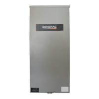
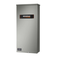
Overview of the automatic transfer switch, its purpose, and its main components like the transfer mechanism.
Description of the single-phase transfer switch mechanism, including its function and connection types.
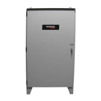
Specifications for utility service and generator disconnect circuit breakers for 100A and 150/200A models.
Guidance on using the data decal for identifying limits and requesting parts or information.
Description of the standard NEMA and UL 3R enclosure type and its protection against environmental factors.
Important safety precautions and recommendations for operating the transfer switch.
Details on the SACM for managing up to four air conditioner loads by shedding them during generator overload.
Overview of the optional SMM for managing various loads, accommodating up to eight individual modules.
Considerations for using SACM and SMMs together, including priority settings and system sizing.
Overview of the installation process, including mounting, connections, and testing the transfer switch.
Instructions and considerations for mounting the transfer switch enclosure vertically to a rigid structure.
Step-by-step guide on how to safely remove the outer and inner panels of the transfer switch enclosure.
Detailed instructions for connecting utility and generator power sources to the transfer switch terminals.
Guidance on connecting generator start and sensing circuit wires, including wire gauge and length recommendations.
Procedure for connecting the SACM to control air conditioner loads using thermostat wiring.
Information on connecting the normally-closed auxiliary contact for customer accessories or remote devices.
Guidance on applying the fault current identification label for NEC compliance and inspection purposes.
Procedures for inspecting the installation and performing functional tests on the transfer switch system.
Step-by-step guide for manually operating the transfer switch, including safety precautions.
Procedure for manually moving the transfer switch to the utility source side, with safety warnings.
Procedure for manually moving the transfer switch to the generator source side, with safety warnings.
Procedure for manually returning the transfer switch to the utility source side.
Steps to check utility power supply voltage and frequency at the transfer switch terminals.
Steps to check generator output voltage and frequency, ensuring compatibility with transfer switch ratings.
Procedures for testing the generator's performance and the transfer switch's response under load conditions.
Steps to verify the proper automatic transfer of loads between utility and generator power sources.
Final checks for installation compliance, system operation verification, and end-user education.
Procedure for safely shutting down the generator while under load or during a utility outage, with safety warnings.
Steps to safely prepare the system for maintenance by disconnecting power sources.
Procedure for testing the load shed functions of the SACM using the test pushbutton.
Instructions for accessing, replacing, and storing the fuse removal tool for the SACM.
Reference to the SMM Owner's/Installation Manual for testing procedures.
Dimensional drawings for 100A Service Entrance and non-Service Entrance, and 150-200A non-Service Entrance models.
Dimensional drawings for the 150/200A Service Entrance model, including an exploded view.
Diagrams showing interconnection for liquid-cooled generators, Part 1 of 2.
Diagrams showing interconnection for liquid-cooled generators, Part 2 of 2.
Diagrams showing interconnection for air-cooled generators, SE and non-SE rated ATS, Part 1 of 2.
Diagrams showing interconnection for air-cooled generators, SE and non-SE rated ATS, Part 2 of 2.
| Brand | Generac Power Systems |
|---|---|
| Model | RXSW100A3 |
| Category | Switch |
| Language | English |