Do you have a question about the Generac Power Systems RXUW200A3 and is the answer not in the manual?
Introduction to the Generac Power Systems Inc. product, emphasizing its design for high performance and efficiency.
Instruction to read and understand the manual completely before using the product to prevent death or serious injury.
General safety guidelines, hazard alerts (DANGER, WARNING, CAUTION), and alert definitions for safe operation.
Details specific electrical hazards associated with the transfer switch, including electrocution risks.
Information on general hazards beyond electrical, including backfeed, jewelry, and enclosure access.
Instructions for carefully unpacking the transfer switch, inspecting for damage, and filing claims.
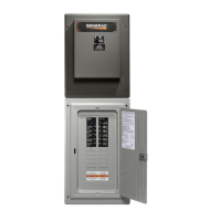
Description of the automatic transfer switch's function, components, and its suitability for optional standby systems.
Details on the transfer switch mechanism for single-phase systems where the neutral line is not switched.
Information on the types of utility service circuit breakers used for 150/200 amp models.
Guidance on using the data decal for switch limits and requesting information or parts.
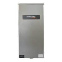
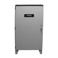
Description of the NEMA 3R enclosure, its protection against weather, and mounting considerations.
Crucial safety warnings and compliance with codes and standards for safe operation of the transfer switch.
Explanation of load management systems, like the Smart A/C Module (SACM), for preventing generator overload.
Detailed description of the SACM, its function in shedding loads, priority levels, and LEDs.
Guidance on generator overload conditions, load shedding, and managing multiple loads with SACM and SMM modules.
List and description of various accessories available for the transfer switch and meter socket.
Overview of the installation procedures, including mounting, wiring, and testing the transfer switch.
Guidelines for mounting the transfer switch enclosure, emphasizing structural support and leveling.
Step-by-step instructions with figures for opening the transfer switch enclosure and removing covers.
Detailed instructions for connecting the utility power source, including terminal connections and code compliance.
Instructions for connecting the generator power source to the transfer mechanism for RXUW models.
Guidance on connecting generator start circuit wires, including wire gauge and length recommendations.
Instructions for connecting the Smart A/C Module (SACM) for controlling air conditioner loads.
Procedure for routing and connecting thermostat cables to the SACM for controlling air conditioner loads.
Information on the normally-closed auxiliary contact for operating accessories and its ratings.
Instructions for applying and completing the fault current identification label for NEC compliance.
Step-by-step guide to install the transfer switch and SACM kit for RBU models, including hardware and connections.
Guidance on performing functional tests after installation, emphasizing compliance with codes and manual order.
Instructions for safely performing manual operation of the transfer switch, including precautions against transferring under load.
Procedure to manually move the transfer switch to the utility source side, including handle operation.
Procedure to manually move the transfer switch to the generator source side, including handle operation.
Instructions for manually returning the transfer switch to the utility source side.
Note on using a Digital Multimeter (DMM) with LowZ setting for accurate voltage measurements.
Steps to check utility power supply voltage and frequency at the transfer switch terminals.
Procedure to check generator output voltage and frequency after it stabilizes and the breaker is closed.
Steps for testing the generator under load conditions, including load application and parameter checks.
Procedure to verify the system's automatic operation, including simulating utility outages and generator start-up.
Critical steps to safely shut down the generator under load or during a utility outage to prevent damage.
Steps to prepare the unit for maintenance by safely shutting down power sources and removing fuses.
Procedure to test the Smart A/C Module (SACM) load shed functions using the test pushbutton.
Instructions for replacing fuses in the SACM housing, including the use of the provided tool and fuse specifications.
Dimensional drawings for the 150-200A SER METER MAIN installation.
Diagrams showing interconnection for liquid-cooled generators, illustrating wiring and connections.
Diagrams showing interconnection for air-cooled generators, illustrating wiring and connections.
| Model | RXUW200A3 |
|---|---|
| Type | Automatic Transfer Switch |
| Rated Amperage | 200A |
| Voltage | 120/240V |
| Phase | Single Phase |
| NEMA Rating | NEMA 3R |
| Operation Mode | Automatic |
| Enclosure Type | Outdoor |
| Compatible Generators | Generac Generators |