SP
IM
SW2
18
LOP
IDLE
CONTROL
COIL
SW3
RED
CONTROL
BOARD
SYSTEM
GRY
GRY
44
ICT
WHT
BRN
11
BLU
STATO R
86
BLK
RED
BLK
P1 P3
P4 P2
CT1
CT2
W1 W3
DK BLU
RED
BLK
BLK
RED
RED
WHT
DK BLU
22
44
33
TB
44B
11
44
44
22
RED(+)
WHT
BA
RED(+)
WHT
AVR
CLOSEST TO
BEARING
0
22
22
WHT
0
GRYGRY
22
WHT
BLK
C2-PLUG C2-CAP
0
L1
L2
R2
R1
18
86
18
11
0
33
33
44B
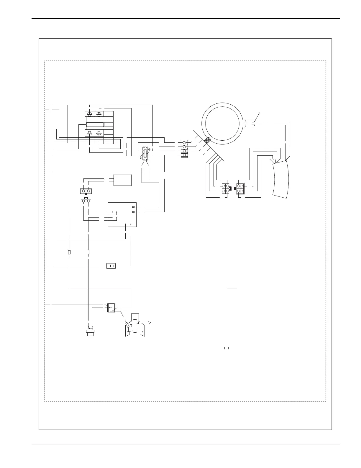
C2 - 4 POS AVR TO ALTERNATOR CONNECTOR,
C1 - 2 POS FREE HANGING CONNECTOR,
AVR - AUTOMATIC VOLTAGE REGULATOR
SP - SPARK PLUG
HM - HOUR METER
SW2 - RUN-STOP SWITCH
SW1 - VOLTAGE SELECTOR SWITCH,
TB - ALTERNATOR TERMINAL BLOCK
SW3 - IDLE CONTROL SWITCH
LOP - LOW OIL PRESSURE SWITCH
IM - IGNITION MODULE
GND - GROUND STUD
ICT - IDLE CONTROL TRANSFORMER
NEUT - NEUTRAL STUD
BA - BRUSH ASSEMBLY
120/240V, 30A, 3PDT
CAP TO PLUG
PLUG TO CAP
LEGEND
- INTERCONNECT
BLK
BLK
BLK
C1-CAP
BLU
BLU
GRN
WHT
BLU
BLU
GRN
WHT
C1-PLUG
2
1
15A/2P
C.B.
44A
11A
11A
44A
MODULE
GFCI
11
WIRING - DIAGRAM
XP4000 PORTABLE
DRAWING #: 0H8536
REVISION: D
DATE: 05/20/11

 Loading...