BATTERY
0
0
13
0
18
SW2
18
56
SC
SC
SM
44B
30A/1P
C.B.
30A/2P
C.B.
G
11A
X
WHT
11C
T1
Y
T1A
0
X
0
G
WHT
30A
TWISTLOCK
120V/240V
22
TWISTLOCK
120V
30A
22
11B
11D
44B
0
20A/1P
C.B.
22
44C
0
44B
20A/1P
C.B.
44D
44D
22
120V/20A
DUPLEX
120V/20A
22
DUPLEX
SP
IM
12V
(-)
(+)
LOP
SW1
30A/3PDT
T1
22
33
33
33
44A
44A
11A
1
2
3
4
5
6
7
8
9
44A
11A
22
0
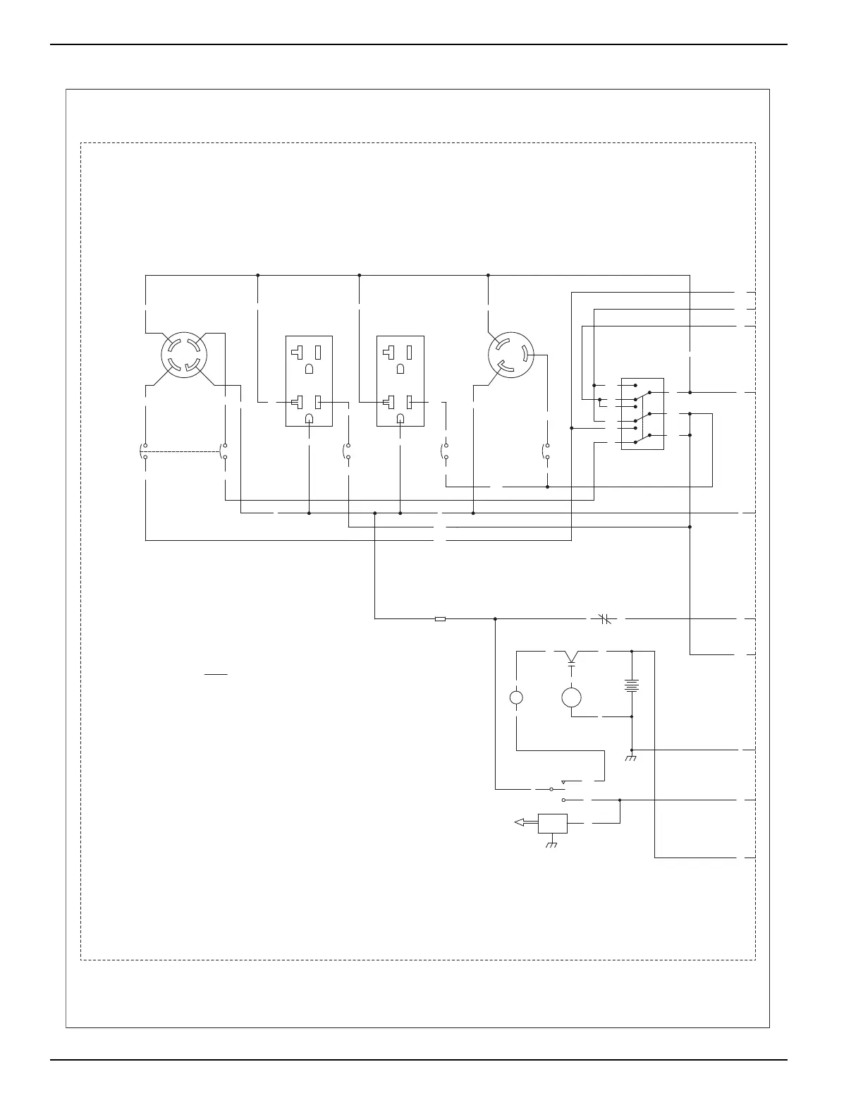
BA - BRUSH ASSEMBLY
C3 - 4 POS AVR TO ALTERNATOR CONNECTOR
120/240V, 30A, 3PDT
SW1 - VOLTAGE SELECTOR SWITCH,
TB - ALTERNATOR TERMINAL BLOCK
AVR - AUTOMATIC VOLTAGE REGULATOR
HM - HOUR METER
NEUT - NEUTRAL STUD
F1 - FUSE 1.5 AMP, SLO-BLO
C1 - 4 POS FREE HANGING CONNECTOR
C2 - 2 POS FREE HANGING CONNECTOR
SC - STARTER CONTACTOR
SM - STARTER MOTOR
ICT - IDLE CONTROL TRANSFORMER
GND - GROUND STUD
IM - IGNITION MODULE
LOP - LOW OIL PRESSURE SWITCH
SP - SPARK PLUG
SW3 - IDLE CONTROL SWITCH
SW2 - START-RUN-STOP SWITCH
LEGEND
0
11B
11B
11A
44B
11B
22
8686
18
0
13
0
POSITION SHOWN
120V/240V
BC - BATTERY CHARGER
BCR - BATTERY CHARGE RELAY
13
56
13
(RED)
(BLACK)
16
L14-30R
L5-30R
5-20R 5-20R
SCHEMATIC - DIAGRAM
XP6.5 PORTABLE
DRAWING #: 0H6809
REVISION: D
DATE: 05/20/11

 Loading...