Do you have a question about the General Monitors S104 and is the answer not in the manual?
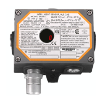
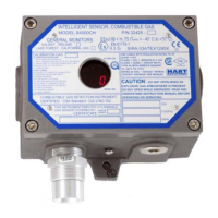
Overview of the Model S104 Enhanced Smart Sensor assembly for detecting combustible gases.
Highlights microprocessor electronics, one-person calibration, 2-digit display, and 4-20mA output.
Lists typical applications for the Model S104, including platforms, facilities, and storage.
Explains the use of a low-temperature catalytic bead to detect combustible gases and convert heat to resistance change.
Details the +24 VDC input and the regulated voltages supplied to internal circuitry.
Describes the microprocessor-based control system, inputs, and outputs like display and 4-20mA signal.
Instructions for checking shipped equipment for damage or discrepancies upon arrival.
Guidance on optimal placement, pointing down, avoiding contaminants, and RFI proximity.
Covers mounting dimensions, conduit sealing, and preventing corrosion due to moisture.
Details the terminal blocks (TB1, TB2) and wiring for power, remote functions, and output signals.
Steps for applying power, checking wiring, and the initial start-up mode indication (SU).
Explains explosion proof rating factors, gap checks, and proper use of entry holes and plugs.
Describes calibration procedures, recommendations, and checking sensor integrity every 90 days.
Lists and explains codes displayed during start-up, calibration, and normal operation.
Details self-diagnostics, fault codes (F1-F9), and actions for correcting issues and recalibration.
Details system specifications like sensor type, life, warranty, and monitored fault conditions.
Provides termination and outline drawings for standard and CE marked units.
Explains configuration codes for calibration signal, display option, sensors, and active channels.
Lists FMRC approved sensors and apparatus, and testing criteria for the Model S104.
| Brand | General Monitors |
|---|---|
| Model | S104 |
| Category | Accessories |
| Language | English |