Sensor Assembly
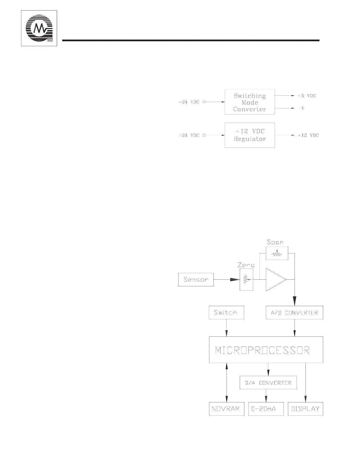
2.2 Power Supply
The Model S104 operates from a +24 VDC
(nominal) input. This unregulated source is
fed to a converter board that produces volt-
ages (see figure 3). These signals are the
source for operating all of the circuitry on the
control and the display boards, and supplying
the sensor with power. Terminal connections
inside of the housing have been provided for
accepting the input power.
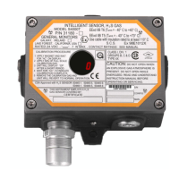
2.3 Control Electronics
The control electronics are centered around an
eight bit microprocessor (figure 4). The Sen-
sor Signal, the CAL Switch, the Non-Volatile
Memory (NOVRAM), and certain Fault con-
ditions are monitored as inputs. By process-
ing these inputs, the following outputs are
generated: 4-20mA Output Signal, Digital
Display Indications, and Calibration Values
(NOVRAM). As the microprocessor (MPU)
receives and processes the inputs, it deter-
mines what value is output to the display, and
the 4-20mA current generator. When the
CAL Switch is activated, the MPU allows the
user to choose between the Calibration or the
Test Gas Modes. While the unit is in one of
these modes, the MPU will fix the 0-20mA
output signal to 1.5mA (0mA signal is op-
tional for the calibration mode only).
Calibration Mode: When the unit is placed
in this mode, the MPU accepts a ZERO value
and waits for the signal from the sensor to in-
crease and then stabilize. It accepts this final
value as the SPAN value. These values are
stored in NOVRAM and are used to adjust
the digital potentiometers associated with the
Input Amplifier.
figure 3
Test Gas Mode: In this mode, the MPU will
output the gas concentration to the display
while fixing the analog output at 1.5mA.
When the gas concentration drops below 10%
LEL, the unit will return to normal operation.
The purpose of this mode is to check the re-
sponse of the unit to a known level of gas and
determine if calibration is necessary.
figure 4
4
GENERAL MONITORS
Model S104