Operation
Fault Codes & Their Remedies (continued)
F4 = Sensor Reference Bead Error
This fault may occur as a result of one of the
following:
l excessive negative drift
l an open sensor reference bead
l the sensor BLACK wire is disconnected
ACTION - Attempt to recalibrate the unit. If
this is unsuccessful make sure that the
BLACK sensor wire is connected to the termi-
nal block. If both of these actions do not cure
the fault condition, then replace sensor.
F5 = Sensor Active Bead Error
This fault occurs if the sensor active bead be-
comes open circuited or, if the sensor WHITE
or the sensor RED lead becomes disconnected.
ACTION - Check the WHITE and RED wires
or replace the sensor as appropriate.
F6 = Low Supply Voltage
This fault occurs if the supply voltage drops
below +17VDC approximately. ACTION -
Ensure that the supply voltage is at least
+20VDC at the Model S104.
Correcting this Fault will initiate the Start-Up
Mode.
NOTE: With long supply leads, a consider-
able voltage drop may occur due to the elec-
trical resistance of the leads.
The maximum cable resistance which the
Model S104 can tolerate is dependent on the
supply voltage. A maximum of 20 ohms per
conductor (40 ohms loop) at +24VDC mini-
mum, or a maximum of 10 ohms per conduc-
tor (20 ohms loop) at +20VDC minimum.
F7 = EEPROM Verification Failure
This fault occurs during calibration when an
attempt to verify the calibration parameters
just written to the non-volatile memory fails.
The usual cause of this is electrical interfer-
ence corrupting the data (although on rare oc-
casions it may indicate a problem within the
electronics module). ACTION - Place the
magnet over the GMI Logo and the unit will
attempt another EEPROM write and verify.
F8 = Negative Zero Drift
If the zero baseline of the sensor drifts 10% of
full scale below zero for more than 20 seconds
this fault will occur. ACTION - A routine re-
calibration will be required.
F9 = Calibration Check Period Exceeded
If the Model S104 is left in the Test Gas Mode
for more than six minutes without a Test Gas
being applied, this fault will occur. ACTION
- Place the magnet over the General Monitors
Logo to return the unit to normal operation.
NOTE: Anytime a sensor is replaced, the unit
should be disconnected from all alarms, as the
unit may go upscale upon power-up.
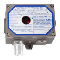
NOTE:
Model S104 without display has
limited fault diagnostic capabilities. It can
sense calibration, sensor and low voltage
faults. See figure 17 for LED sequences.
16
GENERAL MONITORS
Model S104