9
English
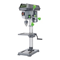
INSTALLING THE TABLE ASSEMBLY
(FIG 4,5)
1. Insert the rack (K) into the geared groove of the table support
(9). Make sure the rack is engaged with the teeth of the gear.
2. Slide the table support and rack assembly down together onto
the column (C). Insert the bottom edge of the rack into the lip
of the column support (C1). Hold its position.
3. Place the column ring (L) bevel side down over the rack.
Tighten the set screw (L1) with 4mm Allen wrench provided to
hold the rack in position.
NOTE: Make sure there is enough clearance to allow the
table to rotate around the column. The ring should sit loosely
over the rack.
4. Insert the table support crank handle (H) into the worm shaft
(B2). Make sure the set screw is aligned to the flat of the shaft
and as close to the table support as possible. Tighten the set
screw.
5. Position the table in the same direction as the base. Tighten
the table support lock handle (7).
INSTALLING HEAD ASSEMBLY, FEED
HANDLES AND CHUCK (FIG 6, 7)
1. With the aid of a second person, carefully lift the head
assembly (A) onto the column top.
NOTE: The head assembly is heavy! Use care when lifting
onto the column.
2. Rotate head assembly until the sides of the pulley housing
cover are parallel with sides of the base.
3. Tighten two set screws (A3) with a Allen wrench until they are
snug.
4. Install three down feed handles (E) into the handle hub (A4).
5. Raise the table to approximately 7 inches below spindle
assembly, and lock the table in place.
6. Place a piece of scrap wood on the table. (See FIG 7)
7. Thoroughly clean the arbor and chuck (F).
8. Twist the chuck to retract the chuck jaws if they are exposed.
9. Install the chuck (F) onto the spindle.
10. Lower the feed handle so that the chuck meets the scrap
wood. Put pressure on the feed handle to seat the chuck onto
the spindle.
REMOVING THE CHUCK
1. Unplug the machine from the power source.
2. Turn the feed handles to lower the chuck to the lowest
position.
3. Place a ball joint separator above the chuck and tap it lightly
with a hammer to cause the chuck to drop from the spindle.
INSTALLING THE BATTERIES FOR THE
LED WORK LIGHT (FIG 8)
• Turn off the work light.
• Push the tab located on the work light battery compartment
cover (22B) down and toward you, then remove it.
• Insert two “AAA” batteries in the work light battery
compartment.
• Replace the work light battery compartment cover.
FIG 5
C
L
L1
7
H
C1
FIG 4
B
C
K
9
B2
FIG 7
SPINDLE
F
FIG 6
A3
E
A4
A
FIG 8
22B