FIG 9
24
a
b
c
FIG 7
17
a
b
c
FIG 8
e
d
English
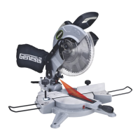
10" Compound Laser Miter Saw
Operator’s Manual GMS15LB
2.
NOTE: To set the positive bevel stop for 45° use the above procedure utilizing a 45° triangle or the 45° side of the
combination square. The 45° bevel adjustment bolts (c-FIG 7) is located on the left lower portion of the bevel knuckle.
LASER ALIGNMENT
WARNING: Laser light – do not stare into the beam, aperture, or into a reflection from a mirror-like surface.
WARNING: Avoid exposure – laser light is emitted from the rear guard aperture. Use of controls or adjustments,
or performance of procedures other than those specified herein may result in hazardous laser light exposure.
WARNING: DO not disassemble the laser module.
WARNING: USE of controls or adjustments or performance of procedures other than those specified herein
may result in hazardous radiation exposure.
WARNING: BE sure that the tool is switched off and unplugged from the power source before performing any
work on the tool. Failure to unplug the saw may result in accidental start-up, causing possible serious personal injury.
OPERATION
WARNING: Always be sure the miter saw is disconnected from the power source before making any
adjustments or setting up prior to cutting. Failure to disconnect or unplug the machine may cause accidental starting,
resulting in serious personal injury.
LOCKING AND UNLOCKING THE CUTTING HEAD
To lock down the cutting head

 Loading...