Do you have a question about the Genie S-60 HC and is the answer not in the manual?
Safety and operating instructions for maintenance and repair procedures.
Lists available service manuals based on serial number ranges for specific models.
Records revisions made to the manual with dates and descriptions of changes.
General safety rules and principles for machine operation and maintenance.
Awareness of hazards, prioritizing personal safety and machine operation.
Guidelines for maintaining a safe work area and handling materials.
Details on tires, wheels, and general machine physical attributes.
Information on boom function speeds, braking distance, and drive speeds.
Details on hydraulic oil types, fluid capacities, and pump specifications.
Torque specifications for manifold components and valve coil resistance.
Critical rules for performing maintenance and handling machines.
Outlines inspection types and frequencies (daily, quarterly, semi-annually, annual, two years).
Form for recording pre-delivery inspection results.
Checklist for recording results of scheduled maintenance inspections.
Procedures for daily/8-hour and 40-hour maintenance checks.
Procedures for 250-hour/quarterly and 400-hour maintenance checks.
Procedures for 500-hour/six-month and 600-hour maintenance checks.
Procedures for 1000-hour/annual maintenance checks.
Procedures for 2000-hour/two-year maintenance checks.
Critical rules for performing repair procedures and handling machines.
Essential steps to take before commencing any repair procedure.
Information about ALC-500 circuit board and joystick calibration.
Procedures for removing and handling platform leveling slave cylinder and rotator.
Procedures for removing and repairing the cable track and boom.
Procedures for RPM adjustment and flex plate service for various engine models.
Procedures for removing and priming the function and drive pumps.
Components and specifications for various hydraulic manifolds.
Safety rules and preparation steps before commencing troubleshooting.
Fault codes related to the control system, identifying error source and type.
Procedure to retrieve fault codes using platform controls.
Procedure to retrieve engine fault codes for Ford models.
Procedure to retrieve fault codes from the platform load sense system.
Overview of electrical and hydraulic schematics provided in this section.
Defines electrical symbols used in schematics for component identification.
Defines hydraulic symbols used in schematics for component identification.
Diagram showing the location of engine relays for Ford models.
Diagram illustrating the locations of various limit switches on the machine.
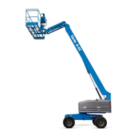
| Lift Capacity | 500 lbs |
|---|---|
| Power Source | Diesel |
| Drive Speed - Stowed | 3.5 mph |
| Gradeability - Stowed | 40% |
| Controls | Proportional |
| Machine Width | 8 ft |
| Drive Speed | 3.5 mph |
| Platform Size | 3 ft x 6 ft |
| Platform Rotation | 160 degrees |
| Vertical Jib Rotation | 135 degrees |
| Swing | 90 degrees |
| Drive | 4-wheel drive |
| Tires | Solid, non-marking |
| Auxiliary Power Unit | DC |
| Ground Clearance | 1 ft |
| Steer Angle | 45 degrees |