Home
Genie
Lifting Systems
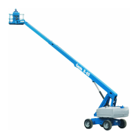
S-60X
Genie S-60X - Service Manual
461 pages
Manual
Specs
Ask a question
Save Page as PDF
To Next Page
To Next Page
Loading...
2
Table of Contents
Main Page
Introduction
2
Serial Number Information
2
Revision History
3
Serial Number Legend
5
Safety Rules
6
Personal Safety
6
Table of Contents
8
Specifications
23
Machine Specifications
23
Performance Specifications
24
Hydraulic Specifications
25
Manifold Component Specifications
26
Ford DSG-423 EFI Engine Specifications
27
Ford MSG-425 EFI Engine Specifications
28
Deutz D2011L03I Engine Specifications
29
Deutz Td2011L04I Engine Specifications
31
Perkins 404-22 Engine Specifications
33
Machine Torque Specifications
34
Trax Torque Specifications
35
Hydraulic Hose and Fitting Torque Specifications
36
Scheduled Maintenance Procedures
39
About this Section
39
Pre-Delivery Preparation
41
Maintenance Inspection Report
43
Checklist a Procedures
45
Inspect the Manuals and Decals
45
Perform Pre-Operation Inspection
46
Perform Function Tests
46
Perform Engine Maintenance
47
Check the High Pressure Hydraulic Filter Condition Indicator
47
Test the Oscillate Axle (if Equipped)
48
S-60 TRAX and S-65 TRAX
48
Perform 30 Day Service
49
Perform Engine Maintenance - Ford and Perkins Models
51
Inspect the Fuel Filter/Water Separator - Diesel Models
51
Check and Adjust the Engine RPM - Perkins Models
53
Grease the Turntable Rotation Bearing and Rotate Gear
54
Replace the Drive Hub Oil
55
Perform Engine Maintenance - Ford Models
57
Perform Engine Maintenance - Perkins Models
57
Checklist B Procedures
58
Inspect the Battery
58
Inspect the Electrical Wiring
59
Check the Exhaust System
60
Inspect the Engine Air Filter - Ford, Deutz and Perkins Models
61
Check the Oil Cooler and Cooling Fins - Deutz Models
61
Inspect the Tires, Wheels and Lug Nut Torque
62
S-60 HC, S60X and S-60XC
62
Confirm the Proper Brake Configuration
63
Check the Drive Hub Oil Level and Fastener Torque
63
Check and Adjust the Engine RPM - Ford and Deutz Models
66
Test the Ground Control Override
67
Check the Oscillate Directional Valve Linkage
67
Test the Platform Self-Leveling
68
Test the Engine Idle Select
68
Test the Fuel Select Operation - Ford Models
69
Test the Drive Brakes
70
Test the Drive Speed - Stowed Position
70
Test the Drive Speed - Raised or Extended Position
71
Test the Alarm Package - Optional Equipment
72
Perform Hydraulic Oil Analysis
73
Inspect the Fuel and Hydraulic Tank Cap Venting Systems
73
Replace the Fuel Filter Element - Perkins Models
74
Inspect the Boom Extend/Retract Cables
76
Perform Engine Maintenance - Deutz Models
77
Perform Engine Maintenance - Ford Models
78
Replace the Engine Air Filter Element - Ford Models
78
Perform Engine Maintenance - Perkins Models
79
Checklist C Procedures
80
Perform Engine Maintenance - Deutz Models
80
Grease the Platform Overload Mechanism (if Equipped
80
S-65, S-60 TRAX and S-65 TRAX
80
Test the Platform Overload System, S-60 and S-65 (if Equipped)
81
S-60 TRAX and S-65 TRAX
81
Test the Platform Load Sense System, S60 HC
84
Replace the Fuel Filter/Water Separator Element - Perkins Models
86
Replace the Engine Air Filter Element - Deutz and Perkins Models
88
Check the Safety Envelope Limit Switches and Angle Sensor, S-60X and S-60XC
88
Perform Engine Maintenance - Perkins Models
91
Perform Engine Maintenance - Ford Models
91
Checklist D Procedures
92
Check the Boom Wear Pads
92
Check the Turntable Rotation Bearing Bolts
93
Inspect for Turntable Bearing Wear
94
Replace the Drive Hub Oil
95
Check the Free-Wheel Configuration
97
Replace the Hydraulic Filters
99
Perform Engine Maintenance - Deutz Models
101
Checklist E Procedures
102
Test or Replace the Hydraulic Oil
102
Perform Engine Maintenance - Deutz Models
104
Replace the Boom Extend/Retract Cables
105
Repair Procedures
107
Platform Controls
108
Circuit Board
108
Remove ALC-500 Circuit Board
108
Joysticks
109
How to Calibrate Joystick
109
Platform Components
115
Platform Leveling Slave Cylinder
115
Platform Rotator
116
Platform Overload System, S-60, S-65, S-60 TRAX and S-65 TRAX (if Equipped)
118
Platform Load Sense System, S-60 HC
120
Jib Boom
124
Jib Boom Lift Cylinder
125
Boom Components
126
Cable Track
126
Boom
131
Boom Lift Cylinder
134
Boom Extension Cylinder
135
Boom Extend/Retract Cables
138
Platform Leveling Master Cylinder
141
Primary Boom Angle Sensor S-60X and S-60XC
142
Engines
143
RPM Adjustment - Ford and Deutz Models
143
RPM Adjustment - Perkins Models
143
Flex Plate
143
Engine Fault Codes - Ford Models
148
Hydraulic Pumps
149
Function Pump
149
Drive Pump
150
Manifolds
152
Function Manifold Components
152
Valve Adjustments - Function Manifold
155
Jib Boom / Platform Rotate Manifold Components
156
Brake/Two-Speed Manifold Components (to SN 25201)
157
Brake/Two-Speed Manifold Components (from SN 25202)
158
Turntable Rotation Manifold Components
159
Oscillate Directional Valve Components
160
Valve Adjustments - Oscillate Relief Valve
162
Drive Oil Diverter Manifold (Welder Option)
163
Traction Manifold Components, 2WD
164
Valve Adjustments, 2WD Traction Manifold
165
Traction Manifold Components, 4WD (from SN 21001 to 21231)
166
Traction Manifold Components, 4WD (after SN 21231)
168
Valve Adjustments, 4WD Traction Manifold
170
Hydraulic Generator Manifold Components, 3Kw (after SN 21396)
171
Valve Coils
172
Turntable Rotation Components
174
Turntable Rotation Assembly
174
Axle Components
176
Track Components
177
Fault Codes
181
Electrical Symbols Legend
210
Hydraulic Symbols Legend
211
Limit Switch Location Legend
212
Ford Engine Relay Layout
213
Ford DSG-423 Engine Wire Harness
215
Ford MSG-425 Engine Wire Harness
217
Electrical Schematic, Options (All Models)
219
Wiring Diagram, Belt Driven Generator
221
Wiring Diagram, 3Kw Hydraulic Generator
223
Wiring Diagram, 12Kw Hydraulic Generator - Welder Option
225
Electrical Schematic, 12Kw Hydraulic Generator Welder Option
227
Hydraulic Schematic, 2WD Models (from SN 21001 to 21396)
231
Hydraulic Schematic, 2WD Models (after SN 21396)
233
Hydraulic Schematic, 4WD Models (from SN 21001 to 21396)
235
Hydraulic Schematic, 4WD Models (after SN 21396)
237
Electrical Schematics - ANSI/CSA
239
Electrical Schematic, S-65 Ford Engine Models (ANSI / CSA)
239
Ground Control Box Terminal Strip Wiring Diagram
243
Ford Engine Models (ANSI / CSA)
245
Ground Control Box Switch Panel Wiring Diagram
245
Ford Engine Models (ANSI / CSA)
246
Platform Control Box Wiring Diagram
247
Ford Engine Models (ANSI/CSA)
249
Platform Control Box Switch Panel Wiring Diagram
249
Ford Engine Models (ANSI / CSA)
250
Electrical Schematic, S-65/S60 TRAX/S65 TRAX Deutz D2011L03I Models (ANSI / CSA)
251
Electrical Schematic, S-65/S60 TRAX/S65 TRAX Deutz Td2011L04I Models (ANSI / CSA)
255
S60 TRAX/S65 TRAX Deutz Engine Models
260
Deutz Engine Models (ANSI / CSA)
261
Deutz Engine Models (ANSI/CSA)
261
S60 Trax/S65 Trax
261
Deutz Engine Models (ANSI / CSA)
262
Deutz Engine Models (ANSI / CSA)
263
Deutz Engine Models (ANSI/CSA)
264
Deutz Engine Models (ANSI/CSA)
265
Deutz Engine Models (ANSI / CSA)
266
Electrical Schematic, S-65/S60 TRAX/S65 TRAX
267
Perkins Engine Models (ANSI/CSA)
267
Perkins Engine Models (ANSI / CSA)
269
Perkins Engine Models (ANSI/CSA)
269
Perkins Engine Models (ANSI / CSA)
270
Perkins Engine Models (ANSI / CSA)
271
Perkins Engine Models (ANSI / CSA)
274
Perkins Engine Models (ANSI / CSA)
275
Perkins Engine Models (ANSI/CSA)
277
Perkins Engine Models (ANSI/CSA)
278
Electrical Schematics - ANSI/CSA
279
Electrical Schematic, S-60X and S-60XC
279
Ford Engine Models (ANSI/CSA)
279
Ford Engine Models (ANSI/CSA)
280
Ford Engine Models (ANSI/CSA)
281
Ford Engine Models (ANSI/CSA)
282
Ground Control Box Terminal Strip Wiring Diagram, S-60X and S-60XC
283
Ford Engine Models (ANSI/CSA)
283
Ground Control Box Switch Panel Wiring Diagram S-60X and S-60XC
285
Ground Control Box Switch Panel Wiring Diagram
285
Platform Control Box Wiring Diagram, S-60X and S-60XC
287
Platform Control Box Switch Panel Wiring Diagram S-60X and S-60XC
289
Platform Control Box Switch Panel Wiring Diagram
289
Electrical Schematic, S-60X and S-60XC
291
Deutz D2011L03I Models (ANSI/CSA)
291
Electrical Schematic, S-60X and S-60XC
292
Deutz Td2011L04I Models (ANSI/CSA)
295
Ground Control Box Terminal Strip Wiring Diagram S-60X and S-60XC
299
Deutz Engine Models (ANSI/CSA)
299
Ground Control Box Switch Panel Wiring Diagram S-60X and S-60XC
301
Platform Control Box Wiring Diagram, S-60X and S-60XC
303
Platform Control Box Switch Panel Wiring Diagram, S-60X and S-60XC
305
Electrical Schematic, S-60X and S-60XC
307
Perkins Engine Models (ANSI/CSA)
307
Ground Control Box Terminal Strip Wiring Diagram S-60X and S-60XC
311
Ground Control Box Switch Panel Wiring Diagram, S-60X and S-60XC
313
Platform Control Box Wiring Diagram S-60X and S-60XC
316
Platform Control Box Switch Panel Wiring Diagram, S-60X and S-60XC
317
Electrical Schematics - CE
319
Electrical Schematic
319
Ford Engine Models (CE) (from SN 21001 to 22516)
319
Electrical Schematic
320
Ford Engine Models (CE) (after SN 22516)
323
Ground Control Box Terminal Strip Wiring Diagram S-60/S-65 Ford Engine Models (CE) (from SN 21001 to 22516)
327
Ground Control Box Terminal Strip Wiring Diagram, S-60/S-65 Ford Engine Models, (CE) (after SN 22516)
330
Ground Control Box Switch Panel Wiring Diagram
331
Ford Engine Models (CE)
331
Platform Control Box Wiring Diagram
333
Ford Engine Models (CE)
333
Platform Control Box Switch Panel Wiring Diagram
335
Ford Engine Models (CE)
335
Electrical Schematic, S-60/S-65/S60 TRAX/S65 TRAX
337
Deutz D2011L03I Models (CE)
337
Electrical Schematic, S-60/S-65/S60 TRAX/S65 TRAX
338
Deutz Td2011L04I Models (CE)
341
Ground Control Box Terminal Strip Wiring Diagram, S-60/S-65 S60 TRAX/S65 TRAX Deutz Engine Models (CE)
345
Ground Control Box Switch Panel Wiring Diagram S-60/S-65/S60 TRAX/S65 TRAX Deutz Engine Models (CE)
347
Platform Control Box Wiring Diagram S-60/S-65/S60 TRAX/S65 TRAX Deutz Engine Models (CE)
349
Platform Control Box Wiring Diagram, S-60/S-65/S60 TRAX/S65 TRAX
349
Platform Control Box Wiring Diagram, S-60/S-65/S60 TRAX/S65 TRAX
350
Platform Control Box Switch Panel Wiring Diagram S-60/S-65/S60 TRAX/S65 TRAX Deutz Engine Models (CE)
351
Electrical Schematics - CE
353
Electrical Schematic, S-60/S-65/S60 TRAX/S65 TRAX
353
Perkins Engine Models (CE)
353
Ground Control Box Terminal Strip Wiring Diagram S-60/S-65/S60 TRAX/S65 TRAX Perkins Engine Models (CE)
357
Ground Control Box Switch Panel Wiring Diagram S-60/S-65/S60 TRAX/S65 TRAX Perkins Engine Models (CE)
359
Platform Control Box Wiring Diagram S-60/S-65/S60 TRAX/S65 TRAX Perkins Engine Models (CE)
361
S60 TRAX/S65 TRAX Perkins Engine Models (CE)
361
Electrical Schematic, S-60 HC (CE)
365
Chassis Wiring Diagram, S-60 HC (CE)
367
Ground Control Box Terminal Strip Wiring Diagram, S-60 HC (CE) (from SN 21001 to 21287)
369
Ground Control Box Terminal Strip Wiring Diagram S-60 HC
369
(CE) (after SN 21287)
371
Platform Control Box Wiring Diagram, S-60 HC (CE)
373
Electrical Schematics - AS, from SN 21001 to 21629
375
Electrical Schematic
375
Ford Engine Models (AS) (from SN 21001 to 21629)
375
Ground Control Box Terminal Strip Wiring Diagram S-60/S-65 Ford Engine Models (AS) (from SN 21001 to 21629)
379
AS, from SN 21001 to 21629
381
Ground Control Box Switch Panel Wiring Diagram S-60/S-65 Ford Engine Models (AS) (from SN 21001 to 21629)
382
Platform Control Box Wiring Diagram S-60/S-65 Ford Engine Models (AS) (from SN 21001 to 21629)
383
Platform Control Box Switch Panel Wiring Diagram S-60/S-65 Ford Engine Models (AS) (from SN 21001 to 21629)
386
Electrical Schematic, S-60/S-65/S60 TRAX/S65 TRAX Deutz D2011L03I Models (AS) (from SN 21001 to 21629)
387
Electrical Schematic, S-60/S-65/S60 TRAX/S65 TRAX Deutz Td2011L04I Models (AS) (from SN 21001 to 21629)
391
Ground Control Box Terminal Strip Wiring Diagram
395
S60 TRAX/S65 TRAX Deutz Engine Models (AS) (from SN 21001 to 21629)
397
Ground Control Box Switch Panel Wiring Diagram
398
S60 TRAX/S65 TRAX Deutz Engine Models (AS) (from SN 21001 to 21629)
399
Platform Control Box Wiring Diagram
399
S60 TRAX/S65 TRAX Deutz Engine Models (AS) (from SN 21001 to 21629)
401
Platform Control Box Switch Panel Wiring Diagram
402
Electrical Schematic, S-60/S-65/S60 TRAX/S65 TRAX Perkins Engine Models (AS) (from SN 21001 to 21629)
403
S60 TRAX/S65 TRAX Perkins Engine Models (AS) (from SN 21001 to 21629)
404
Perkins Engine Models (AS) (from SN 21001 to 21629)
405
Platform Control Box Wiring Diagram
411
S60 TRAX/S65 TRAX Perkins Engine Models (AS) (from SN 21001 to 21629)
412
Platform Control Box Switch Panel Wiring Diagram
414
Electrical Schematics - AS, after SN 21629
415
Electrical Schematic
415
Ford Engine Models (AS) (from SN 21630 to 22516)
415
Electrical Schematic
416
Ford Engine Models (AS) (after SN 22516)
419
Ground Control Box Terminal Strip Wiring Diagram, S-60/S-65 Ford Engine Models (AS) (from SN 21630 to 22516)
423
Ground Control Box Terminal Strip Wiring Diagram, S-60/S-65 Ford Engine Models (AS) (after SN 22516))
426
Ground Control Box Switch Panel Wiring Diagram, S-60/S-65 Ford Engine Models (AS) (after SN 21629)
427
Platform Control Box Wiring Diagram
429
Ford Engine Models (AS) (after SN 21629)
430
Platform Control Box Switch Panel Wiring Diagram, S-60/S-65 Ford Engine Models (AS) (after SN 21629)
431
Electrical Schematic, S-60/S-65/S60 TRAX/S65 TRAX Deutz D2011L03I Models (AS) (after SN 21629)
433
Electrical Schematic, S-60/S-65/S60 TRAX/S65 TRAX Deutz Td2011L04I Models (AS) (after SN 21629)
437
Ground Control Box Terminal Strip Wiring Diagram S-60/S-65/S60 TRAX/S65 TRAX Deutz Engine Models (AS) (after SN 21629)
441
Deutz Engine Models (AS) (after SN 21629)
441
Platform Control Box Switch Panel Wiring Diagram
448
Electrical Schematic, S-60/S-65/S60 TRAX/S65 TRAX Perkins Engine Models (AS) (after SN 21629)
449
Ground Control Box Terminal Strip Wiring Diagram S-60/S-65/S60 TRAX/S65 TRAX Perkins Engine Models (AS) (after SN 21629)
453
Ground Control Box Switch Panel Wiring Diagram
456
Perkins Engine Models (AS) (after SN 21629)
456
Other manuals for Genie S-60X
Service And Repair Manual
402 pages
Operator's Manual
69 pages
Need help?
Do you have a question about the Genie S-60X and is the answer not in the manual?
Ask a question
Genie S-60X Specifications
Print Specification
General
Horizontal Reach
50 ft (15.24 m)
Weight
16, 700 lb (7, 575 kg)
Fuel Type
Diesel
Ground Clearance
1 ft (0.30 m)
Steering
4-wheel
Related product manuals
Genie S-60 HC
407 pages
Genie S-45 XC
15 pages
Genie SX-180
77 pages
Genie GTH-4013 SX
225 pages
Genie GTH-4017 SX
225 pages
Genie Superlift SL-5
76 pages
Genie Superlift SL-10
76 pages
Genie GTH-2506 Stage A
98 pages
Genie Super Tower ST-25
24 pages
SUPERLIFT Contractor SLC-12
67 pages
SUPERLIFT Contractor SLC-24
67 pages
SUPERLIFT Contractor SLC-18
67 pages