Do you have a question about the Genie S-60 and is the answer not in the manual?
Provides essential safety rules and operating instructions for machine operation.
Guidelines for individual safety awareness and machine operation priorities.
Rules and precautions for maintaining a safe work environment.
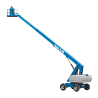
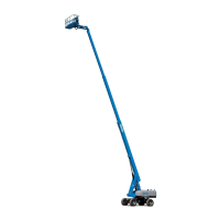
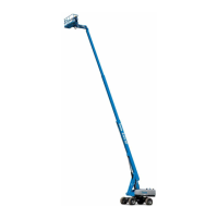
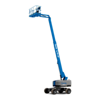
Details on stowed and operational dimensions and capacities.
Information on drive speeds, boom function speeds, and gradeability.
Technical data for the hydraulic system, pumps, and manifolds.
Engine specifications for the Ford LRG-425 EFI model.
Engine specifications for the Deutz F4L 1011F model.
Engine specifications for the Perkins 704-30 model.
Torque values for hydraulic hose and fitting installations.
Details on the engines powering the machine.
Explanation of the hydraulic system's function and components.
Overview of the machine's electrical system.
Description of drive speed and drive enable limit switches.
Explanation of ground and platform control operations.
Essential safety and procedural guidelines for maintenance.
Explanation of symbols used in maintenance procedures.
Overview of inspection frequencies and corresponding checklists.
Guidance on using and storing the maintenance inspection report.
Ensures operator and safety manuals are present and legible.
Verifies all safety and instructional decals are in place and legible.
Checks the entire machine for damage and missing components.
Procedure to verify the engine oil level.
Procedure to check the engine coolant level.
Inspects for fuel leaks to ensure safe operation.
Procedure to verify the hydraulic oil level.
Inspects for hydraulic oil leaks.
Ensures proper tire pressure for stability and handling.
Verifies proper axle oscillation for machine stability.
Checks the functionality of all platform and ground controls.
Verifies the auxiliary power system functions correctly.
Checks the tilt sensor alarm function.
Verifies the operation of drive speed and enable limit switches.
Procedure to drain the fuel filter/water separator on diesel models.
Checks the condition of the engine air filter.
Sequence of procedures for the initial 30-day service interval.
Checks the radiator for leaks, damage, and airflow restriction.
Inspects battery condition, connections, and fluid levels.
Procedure for changing engine oil and filter on gasoline/LPG models.
Checks electrical wiring for damage or loose connections.
Inspects oil cooler and fins for debris and damage.
Inspects engine belts for condition and proper tension.
Procedure for replacing fuel filters on gasoline/LPG models.
Inspects the exhaust system for damage, leaks, and tightness.
Verifies the condition indicator for the hydraulic tank return filter.
Checks tires and wheels for damage and verifies lug nut torque.
Ensures the drive hub disconnect caps and free-wheel valve are correctly set.
Procedure to check and fill oil levels in drive hubs.
Adjusts low and high idle engine RPM settings.
Verifies the proper function of the machine's key switch.
Checks the functionality of all emergency stop buttons.
Verifies the ground control override function for safe operation.
Inspects the linkage for the directional valve on oscillating axle models.
Verifies automatic platform self-leveling throughout the boom cycle.
Checks the functionality and audibility of the machine's horn.
Verifies the proper operation of the foot switch.
Checks the functionality of the engine idle select switch.
Verifies the ability to select and switch between gasoline and LPG fuels.
Ensures the drive enable system operates correctly for safety.
Checks the drive brake function for smooth operation and effectiveness.
Verifies the drive function response and speed in the stowed position.
Verifies drive function response and speed when raised or extended.
Checks the functionality of travel alarms, descent alarms, and beacons.
Procedure for performing hydraulic oil analysis.
Procedure for replacing the hydraulic tank return filter.
Checks the fuel tank cap venting system for proper function.
Procedure for replacing the engine air filter element.
Procedure for replacing spark plugs on gasoline/LPG models.
Inspects the engine belt for condition and proper tension on Deutz models.
Procedure to check engine valve clearances on Deutz Diesel models.
Procedure to replace the fuel filter/water separator on Perkins Diesel models.
Procedure to replace the fuel filter element on Perkins Diesel models.
Procedure for changing engine oil and filter on Perkins Diesel models.
Checks the glow plugs on Perkins Diesel models.
Checks engine coolant specific gravity for cooling system efficiency.
Procedure to replace the PCV valve on gasoline/LPG models.
Measures wear pads and checks for proper boom movement.
Verifies the machine is not in free-wheel configuration without knowledge.
Ensures turntable bearing mounting bolts are torqued correctly.
Applies lubrication to the turntable bearing and rotate gear.
Procedure for replacing drive hub oil for performance and service life.
Procedure for replacing the drive loop hydraulic filter.
Procedure for changing engine oil and filter on Deutz Diesel models.
Cleans the fuel pump strainer for optimal engine performance.
Procedure to replace the diesel fuel filter/water separator on Deutz models.
Procedure for changing fuel hoses on Deutz Diesel models.
Procedure to check engine valve clearances on Perkins Diesel models.
Cleans the engine breather assembly on Perkins Diesel models.
Procedure for testing or replacing the hydraulic oil.
Procedure to change or recondition engine coolant.
Procedure for changing fuel hoses on gasoline/LPG models.
Procedure to replace the engine air breather on Perkins Diesel models.
Greases steer axle wheel bearings on 2WD models.
Checks fuel injectors on Perkins Diesel models.
Essential steps and safety precautions before starting troubleshooting.
Key safety and procedural guidelines for troubleshooting.
Guidance on using troubleshooting flow charts.
List of fault codes, their problems, causes, and solutions.
Troubleshooting steps for an engine that will not crank.
Troubleshooting for gasoline/LPG engines that crank but don't start.
Troubleshooting for gasoline/LPG engines that die after cranking.
Troubleshooting for diesel engines that crank but don't start.
Troubleshooting for LPG start issues on gasoline/LPG models.
Troubleshooting for gasoline start issues on LPG/gasoline models.
Troubleshooting for inoperative high idle on gasoline/LPG models.
Troubleshooting for inoperative low idle on gasoline/LPG models.
Troubleshooting for inoperative high idle on diesel models.
Troubleshooting for inoperative low idle on diesel models.
Troubleshooting when all functions are inoperative but the engine runs.
Troubleshooting when lift/steer functions fail but drive functions work.
Troubleshooting for inoperative ground controls with working platform controls.
Troubleshooting for inoperative platform controls with working ground controls.
Troubleshooting steps for an inoperative boom up function.
Troubleshooting steps for an inoperative boom down function.
Troubleshooting steps for an inoperative boom extend function.
Troubleshooting steps for an inoperative boom retract function.
Troubleshooting steps for an inoperative turntable rotate left function.
Troubleshooting steps for an inoperative turntable rotate right function.
Troubleshooting for failure of all platform leveling functions.
Troubleshooting steps for an inoperative platform level up function.
Troubleshooting steps for an inoperative platform level down function.
Troubleshooting steps for an inoperative platform rotate left function.
Troubleshooting steps for an inoperative platform rotate right function.
Troubleshooting steps for an inoperative oscillate function.
Troubleshooting steps for an inoperative jib boom up function.
Troubleshooting steps for an inoperative jib boom down function.
Troubleshooting steps for an inoperative steer left function.
Troubleshooting steps for an inoperative steer right function.
Troubleshooting for inoperative drive functions.
Troubleshooting for inoperative drive forward or reverse functions.
Troubleshooting steps for an inoperative traction function.
Troubleshooting for a machine that will not drive at full speed.
Troubleshooting for machines driving at full speed when raised or extended.
Troubleshooting for a malfunctioning drive enable system.
Troubleshooting steps for inoperative auxiliary functions.
Key safety and procedural guidelines for working with schematics.
Steps before troubleshooting using schematics.
Overview of the schematics section.
Diagrams illustrating the machine's electrical systems.
Diagrams illustrating the machine's hydraulic systems.
List of electrical components with part numbers and manufacturers.
Explanation of symbols used in electrical schematics.
List of abbreviations used in the manual.
Wiring diagram for the Ford LRG-425 EFI engine wire harness.
Electrical schematic for gasoline/LPG models.
Wiring diagram for the ground control box on Deutz Diesel models.
Wiring diagram for the platform control box on gasoline/LPG models.
Electrical schematic for Deutz Diesel models.
Wiring diagram for the platform control box on Deutz Diesel models.
Electrical schematic for Perkins Diesel models.
Wiring diagram for the ground control box on Perkins Diesel models.
Wiring diagram for the platform control box on Perkins Diesel models.
Explanation of symbols used in hydraulic schematics.
Hydraulic schematic for 2WD models with a non-oscillating axle.
Hydraulic schematic for 2WD models with an oscillating axle.
Hydraulic schematic for 4WD models with a non-oscillating axle.
Hydraulic schematic for 4WD models with an oscillating axle.
Key safety and procedural guidelines for repair tasks.
Essential steps and safety precautions before starting repairs.
Explanation of symbols used in repair procedures.
Procedures related to platform control systems.
Maintaining and adjusting joystick controllers.
Adjusting the boom up/down controller settings.
Adjusting the turntable rotation controller settings.
Adjusting boom extend/retract controller settings.
Adjusting the horsepower limiter board for optimal performance.
Procedure for testing the foot switch functionality.
Procedure for testing toggle switch continuity.
Procedures related to platform components.
Procedure for removing the platform.
Procedure to remove and bleed the platform leveling slave cylinder.
Procedure for removing and bleeding the platform rotator.
Procedures for jib boom components specific to S-65 models.
Procedure for removing the jib boom.
Procedure for removing the jib boom lift cylinder.
Procedures related to boom components.
Procedure for removing and repairing the boom cable track.
Procedure for shimming the boom wear pads.
Procedure for removing the boom lift cylinder.
Procedure for removing the extension cylinders.
Procedure for removing the platform leveling master cylinder.
Procedure for removing turntable covers.
Repair procedures specific to the Deutz F4L 1011F engine.
Procedure for adjusting engine RPM.
Procedure for removing and installing the flex plate.
Procedure for removing gauge sending units.
Repair procedures specific to the Perkins 704-30 engine.
Procedure for removing coolant and oil pressure gauge sending units.
Repair procedures specific to the Ford LRG-425 EFI engine.
Information on ignition timing adjustment.
Procedures related to ground control systems.
Procedure for testing single pole double throw control relays.
Procedure to retrieve and clear engine fault codes.
Procedures related to hydraulic pumps.
Procedure for removing the lift/steer pump.
Procedure for removing the drive pump.
Procedures related to hydraulic manifolds.
Identification of components within the function manifold.
Procedures for adjusting relief valves in the function manifold.
Identification of components within the turntable rotation manifold.
Identification of components within the oscillate manifold.
Procedure to adjust oscillate sequencing valve pressure.
Identification of components within the directional valve manifold.
Procedure for setting up the directional valve linkage.
Identification of components within the steer manifold for oscillating models.
Identification of components within the steer manifold for non-oscillating models.
Identification of components within the 2WD drive manifold.
Procedure to adjust charge pressure relief valve in the 2WD drive manifold.
Identification of components within the 4WD drive manifold.
Procedure to adjust charge pressure relief valve in the 4WD drive manifold.
Components for jib boom/platform rotate manifold on S-65 models.
Procedures related to fuel and hydraulic tanks.
Procedure for removing the fuel tank.
Procedure for removing the hydraulic tank.
Procedures related to turntable rotation components.
Procedure for removing the rotation hydraulic motor.
Procedures related to 2WD steering axle components.
Procedure for removing and installing the yoke and hub.
Procedure for removing steering cylinders.
Procedure for removing and adjusting the tie rod.
Procedures related to 4WD steering axle components.
Procedures related to oscillating axle components.
Procedures related to non-steering axle components.
Procedure for removing the drive motor.
Procedure for removing the drive hub.
Procedure for removing the wheel brake.
| Platform Height | 60 ft |
|---|---|
| Gradeability - 4WD | 45% |
| Engine Type | Diesel |
| Platform Width | 30 in |
| Ground Clearance | 1 ft |