7
ENGLISH
G-BAT AUTOMATED SYSTEM
The G-BAT automated system for gates with swing leaves is an
operator which transmits movement to the leaf via a worm screw
system.
A handy release system makes it possible to move the gate ma-
nually in the event of a power cut or operator faults.
The G-BAT operator is available in both the 230/115V version and
in the 24V version.
Before you start installing the operator, read this manual to the
letter.
Store the manual for any future references.
Correct operation and the declared technical characteristics
can be obtained only by respecting the indications in this
manual and using GENIUS accessories and safety devi-
ces.
To ensure an adequate degree of safety for the automated
system, the absence of a mechanical clutch device, calls
for the use of a control unit with an adjustable electronic
clutch device.
The G-BAT operator was designed and built to control vehicle
access – AVOID ANY OTHER USES.
Anything not expressly specified in this manual is not permit-
ted.
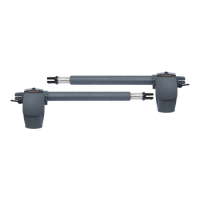
1. DESCRIPTION
Fig. 1
Operator
Transmission pipe
Release key
Rear fastening bracket
Front fastening bracket
Fastening pins
Elastic rings
1.1. TECHNICAL SPECIFICATIONS
Model G-BAT
G-BAT Lento
(slow)
B-BAT
115V
G-BAT
24V
Power suply voltage
and frequency
230Vac 50Hz
115Vac
60Hz
24Vdc
Absorbed power 280 W 350W 70W
Absorbed current 1.2 A 3 A 3 A
Thermal protection 140 °C
Capacitor 8µF 400V
25µF
250V
Max.thrust force
350
daN
300
daN
350
daN
300
daN
Rod stroke 300 mm / 400 mm
Rod linear speed
1.6
cm/sec
1.1
cm/sec
1.85
cm/sec
1.6
cm/sec
Operating ambient temperature
-20 °C — +55°C
Type and use frequency
S3 30%
Intensive
Indicative hour cycles at
20°C
≥30
(≥24)
≥20
(≥16)
≥30
(≥24)
≥100
(≥75)
Operator weight 6.5 Kg / 7Kg
Protection class IP 54
Maximum leaf length
3 m /4 m
To calculate use frequency, refer to paragraph 1.1.1.
For leaves of over 2.5 m, an electrical lock is necessary to
guarantee leaf blocking
1.1.1. GRAPH AND USE FREQUENCY
The curve makes it possible to establish maximum work time (T)
according to use frequency
(F).
With reference to standard
IEC 34-1, the G-BAT gearmo-
tor, with service type S3, can
operate at use frequency
of 30%.
To ensure efficient operation,
operate in the work range
under the curve.
The curve is obtai-
ned at a temperature
of 20°C. Exposure to
direct sun rays can
reduce use frequen-
cy down to 20%.
CALCULATION OF USE FREQUENCY
The percentage of effective work time (opening + closing) com-
pared to total time of cycle (opening + closing + pause times).
Calculation fomula:
Ta + Tc
% F = ––––––––––––––––––– X 100
Ta + Tc + Tp + Ti
Where:
Ta = opening time
Tc = closing time
Tp = pause time
Ti = interval time between one complete cycle and another
1.2. DIMENSIONS
Fig. 2