8
ENGLISH
2. INSTALLATION
2.1. ELECTRIC PREPARATIONS (STANDARD SYSTEM )
To lay cables, use adequate rigid and/or flexible tubes.
To avoid any type of interference, we advise you to always
separate the 230/115Vac power cables from the low vol-
tage command cables, using separate sheaths.
If it is necessary to extend the motor power cable, use a cable
suitable for outdoor mobile laying.
Fig. 3
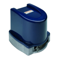
Operator
Control unit
Closing safety devices
Opening and closing safety devices
Opening mechanical stops
Key-operated selector switch
Flashing lamp
Values in brackets refer to 24Vdc operators
2.2. PRELIMINARY CHECKS
To ensure a correctly operating automated system, the structure
of the existing gate or gate to be built must satisfy the following
requirements:
The construction elements of the gate must comply with the
provisions of the EN12604 and EN 12605 standards.
Leaf dimensions must not exceed the values indicated in pa-
ragraph 1.1.
The travel limit mechanical stops, for both opening and closing,
must be installed.
The structure of the leaves must be sufficiently rigid and sturdy,
suitable for the automated system.
Leaf movement must be smooth and free of any jamming during
the entire travel.
Adequately sturdy hinges, in good condition
Check the possibility of fastening the operator, respecting the
installation dimensions – see paragraph 2.3.
Check if an efficient earth plate is present for electrical connec-
tion to the operator.
Do not use the operator to move safety exits or gates installed
on emergency routes (see escape routes).
If a pedestrians door is built into the leaf due to be motorised,
you must add a safety switch on the door, connected to
the stop input, in order to prevent the automated system
working while the door is open.
The condition of the gate structure directly influences the safety
and reliability of the automated system.
We advise you to carry out the metalwork jobs if any, before
installing the operator.
•
•
•
•
•
•
•
•
2.3. INSTALLATION DIMENSIONS
Determine the installation position of the operator by referring to
figure 4, where the minimum off-
ground height is specified.
To determine the operator instal-
lation dimensions, consult figure 5
and the relevant table.
Fig. 5
Version
α
AB
C
D
Z
L
300
90° 145 145
300
100
45
930
110° 125 125 80
400
90° 195 195
400
150
1110
110° 165 165 120
Useful rod stroke maximum dimension minimum dimension
2.3.1. GENERAL RULES FOR DETERMINING THE INSTALLATION DIMENSIONS.
To obtain 90° opening of the leaf: A+B=C.
To obtain leaf opening greater than 90°: A+B<C.
Lower dimensions A and B cause greater leaf peripheral
speed.
Limit the difference between dimension A and dimension B
within 4 centimetres; higher differences cause considerable
leaf peripheral speed variations during closing and opening
movements.
Maintain a Z dimension ensuring that the operator does not
impact the pilaster, while the leaf is closed.
If the dimensions of the pilaster or the position of the hinge
do not allow the operator to
be installed, to respect the
determined dimension A, a
niche must be created on the
pilaster as shown in figure 6.
The dimensions of the niche
must allow smooth installation
of the motor, not limit motor
rotation and not obstruct mo-
tor release operations.
1.
2.
3.
4.
5.
Fig. 4Fig. 4
Fig. 6Fig. 6