19
ENGLISH
ENGLISH
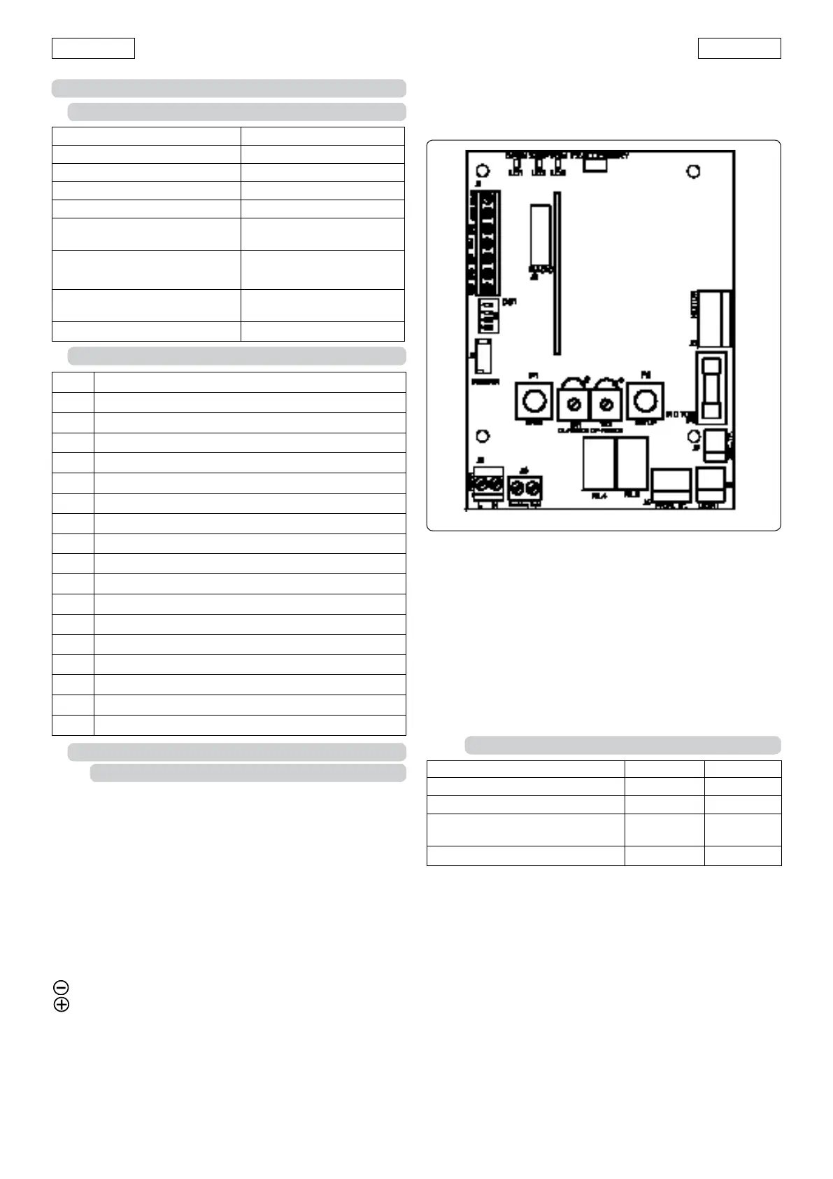
Fig. 26
F1 Motor fuse (G60=10A, G100=15A)
F2 Accessories protection 0.25A automatic reset
J1 Low voltage terminal board for inputs /accessories
J2 Quick connector for 5-pin radio-receiver module
J3 230V power supply input terminal board
J4 Transformer primary connector
J5 Courtesy light connector
J6 Flashing light output terminal board
J7 Transformer secondary connector
J8 Motor output connector
P1 Open pushbutton
P2 Set-up pushbutton
TR1 Closing force adjustment (G100 only))
TR2 Opening force adjustment (G100 only)
DS1 Programming dip-switches
LD1 OPEN input signalling LED
LD2 STOP input signalling LED
LD3 FSW input signalling LED
Power supply 230 Vac 50 Hz
Accessories power supply 24 Vdc
Accessories max. load 200 mA
Ambient temperature -20° ÷ +55°C
Motor protection fuses
Quick connector
for 5-pin radio-receiver
module
Function logics
Automatic/ Semiauto-
matic
Terminal board connections
Open/Stop/Safety devi-
ces/Failsafe/Flasher
Courtesy light timer 2 min
8. G60 and G100 ELECTRONIC CARD
8.1. TECHNICAL SPECIFICATIONS
8.2. 531MPS AND 576MPS CARD COMPONENTS
8.3. DESCRIPTION
8.3.1. Terminal boards and connectors
TERMINAL BOARD J1 (low voltage)
OPEN=Open Command (N.O.)
Any device (pushbutton,
key selector, etc.) which, by clo-
sing a contact, supplies an opening (or closing) pulse to the
door.
To install several Open devices, connect N.O. contacts in
parallel.
STOP=Stop command (N.C.)
Any device (e.g. a pushbutton) which, by opening a contact,
stops door movement.
To install several stop devices, connect the N.C. contacts in
series.
N.B.: if stop devices are not used, jumper connect STOP to
the inputs common contact.
=Inputs/negative accessories supply common contact.
=Accessories supply positive pole (24Vdc 200mA max)
FSW= Closing safety devices contact (N.C.)
Safety devices are all devices (photocells, sensitive edges,
etc.) with N.C. contact which, in case of an obstacle in
the area they protect, cut in to reverse door closing move-
ment.
If the safety devices are activated when the door is locked
or open, they prevent it from closing.
To install several safety devices, connect the N.C. contacts
in series.
N.B.: if safety devices are not connected, jumper connect
FSW to the terminal -TX FSW.
CONNECTOR J2 (low voltage)
Connector J2 is used for quick connection of 5-pin radio-
receiver module
Insert and remove the cards after disconnecting the power
to the operator.
TERMINAL BOARD J3 (high voltage)
Terminal board for 230Vac 50Hz power supply
on the support plate = Earth fixing screw (fig. 27 ref. A).
TERMINAL BOARD J6 (high voltage)
230Vac terminal board for connection of flasher.
8.3.2. Programming Dip-Switches DS1
Failsafe
When activated it enables the photocell function test before
any movement.
Anticrushing sensitivity
In the event of doors with an uneven movement, it allows the
sensitivity of the anticrushing device to be reduced in order to
avoid unwanted activations.
Manual adjustment of force (G100 only)
To use the manual force adjustment, before carrying out lear-
ning turn DS1 switch no.3 to ON and manually adjust the thrust
force with TR1 (closing) and TR2 (opening). The max. delivera-
ble force is 1000N. After adjusting, start the learning procedure
corresponding to the required operation.
If the force is inadequate the learning cycle will not be correctly
concluded. The sensitivity of the anticrushing device depends
No. Function OFF ON
1 Failsafe Active Not active
2 Anticrushing sensitivity Low High
3 Force adjustment (onlyG100) Automatic Manual
4 Carriage speed High Low