Do you have a question about the Genius SW-HF 5.1 6000 and is the answer not in the manual?
Explains special attention and caution notes used throughout the guide.
Lists important safety measures to observe when handling the speaker system.
Provides a general overview of the process for handling defective product returns.
Troubleshooting steps for when the system has no power or the LCD is unlit.
Troubleshooting steps for when the system produces no audio output.
Troubleshooting steps for issues with front channel audio.
Troubleshooting steps for issues with rear channel audio.
Troubleshooting steps for issues with the center channel audio.
Troubleshooting steps for when the woofer is not producing sound.
Troubleshooting steps for when there is no sound from any input source.
Troubleshooting steps for when the remote control is not functioning.
Troubleshooting steps for when the audio system produces unwanted noise.
Troubleshooting steps for when the LCD display is not working correctly.
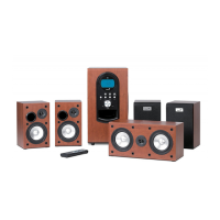
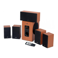
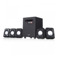
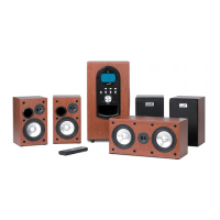
Details the technical specifications for the satellite speakers.
Details the technical specifications for the woofer.
Diagram showing the disassembled components of the subwoofer.
Diagram showing the disassembled components of the center satellite speaker.
Diagrams showing the disassembled components of the front and rear satellite speakers.
Lists the part numbers and descriptions for the woofer components.
Lists the part numbers and descriptions for the center speaker components.
Lists the part numbers and descriptions for the rear speaker components.
Lists the part numbers and descriptions for the front speaker components.
Schematic diagram for the Input PCB of the SW-HF 5.1 6000 system.
Schematic diagram for the Control (CON) PCB of the SW-HF 5.1 6000 system.
Schematic diagram for the Amplifier (AMP) PCB of the SW-HF 5.1 6000 system.
Schematic diagram for the SWAMP and SATSP PCBs of the SW-HF 5.1 6000 system.
Schematic diagram for the Remote Control (REM) PCB of the SW-HF 5.1 6000 system.
Photograph of the Input PCB for the SW-HF 5.1 6000 system.
Photograph of the Control (CON) PCB for the SW-HF 5.1 6000 system.
Photograph of the Amplifier (AMP) PCB for the SW-HF 5.1 6000 system.
Photograph of the SWAMP PCB for the SW-HF 5.1 6000 system.
Photograph of the SATSP PCB for the SW-HF 5.1 6000 system.
Photograph of the Remote Control (REM) PCB for the SW-HF 5.1 6000 system.
| Type | 5.1 Speaker System |
|---|---|
| Frequency Response | 20 Hz - 20 kHz |
| Input Sensitivity | 500 mV |
| Input Impedance | 10 kΩ |
| Remote Control | Yes |
| Subwoofer Output Power | 100 W |
| Input Connectors | RCA |
| Driver Unit Satellite | 3 inches |