10
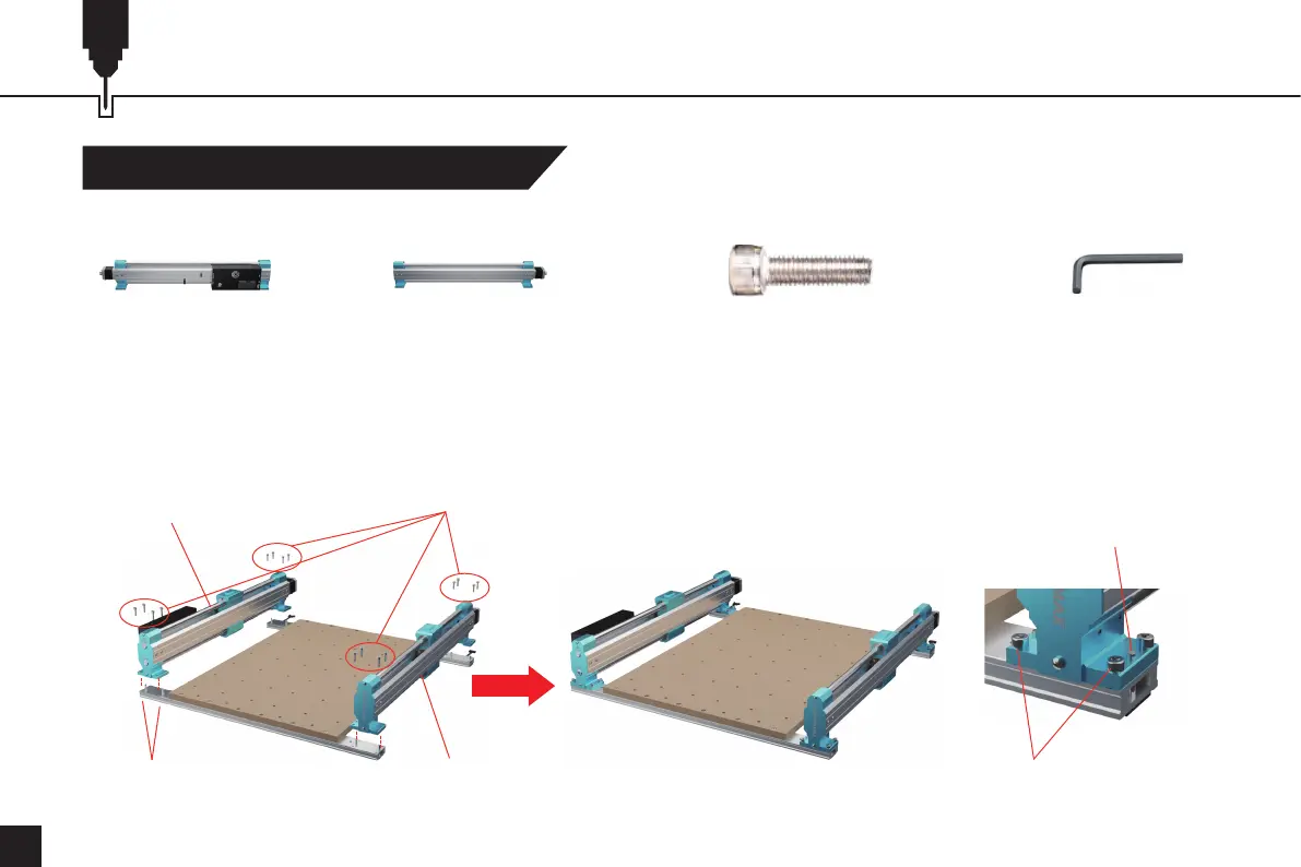
Mechanical Installation
1. Place the Y-axis left and right (YL&YR) module positioning holes through the dowel pins.
2. Use (16) M5 x 20mm screws to mount the YL&YR module to the front and rear plates.
3. Tighten the screws just screwed in on the MDF spoilboards.
4mm Allen Wrench
STEP 3 Installing Y-Axis Assemblies
Y-axis Module (Left) (16) M5×20 Socket Head Cap ScrewY-axis Module (Right)
What you need:
Y-axis Module (Left)
(8) D5-L25 Dowel Pin Y-axis Module (Right)
M5×20 Socket Head Cap Screw
Dowel Pin
(16) M5×20 Socket Head Cap Screw