Geometrics Inc. G-882 Cesium Marine Magnetometer Page 103
Appendix A – Optically Pumped Magnetometer Theory
Note: The following section is provided for information purposes only.
Understanding this theoretical discussion is not required for proper operation of
the magnetometer.
For purposes of this discussion, the ambient magnetic field or earth's magnetic
field is called H
0
. A separate magnetic field generated by an AC signal applied to
a coil inside the sensor is called H
1
. Refer to the drawing on the next page for the
following discussion.
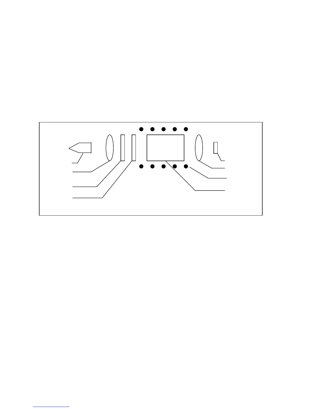
G−882 CESIUM SENSOR
To initiate operation of the sensor, the lamp oscillator's RF power increases until
the lamp strikes (plasma ignites and fluoresces). The lamp oscillator then
reduces its power to produce the regulated amount of light. The heater warms the
absorption cell until a Cesium vapor is formed. A lens bends the light from the
lamp to parallel rays. The lamp produces many spectral lines but only one line in
the infrared region is employed. All of the other light is blocked by a high grade
optical filter.
The infrared line of interest is then passed through a split-circular polarizer. On
one side of the polarizer the transmitted light has an electrostatic vector that
advances with a right-handed rotation. For conceptual purposes, it can be said
that all of the photons in this light have the same right-hand spin direction. The
light transmitted through the other side of the split-circular polarizer produces light
in which the vector advances with a left-handed rotation, therefore having the
opposite spin. Both circular polarized light beams pass through the absorption
cell. Because there is a buffer gas in the cell, the single cell can be considered as
two separate cells, each having the opposite sense polarized light passed through

 Loading...