EasyManuals Logo

GeoVision GV Series Hardware Installation Guide

GeoVision GV Series
12 pages
To Next Page IconTo Next Page
To Previous Page IconTo Previous Page
Page #8 background imageLoading...
Page #8 background image
On the back side, make sure the black plastic clips are slightly
above the ceiling board and pointing outward.
4
From the front side of the camera, tighten the screws.
5
Place the camera cover for in-ceiling mount on top of the camera
and put on the in-ceiling cover.
6
GV-FE2302 / 3402 / 5302 and GV-FE3403 / 5303
Packing List
Camera Cover
(Hard Ceiling Mount)
Camera Cover
(In-Ceiling Mount)
IR LED Ring
(GV-FE3403 / 5303)
Fisheye Camera
PoE Converter set
(including 1 module, 1 DC Power Y-cable, 1 RJ-45 cable and 3 screws)
(GV-FE3403 / 5303 only)

Other manuals for GeoVision GV Series

Questions and Answers:

Question and Answer IconNeed help?

Do you have a question about the GeoVision GV Series and is the answer not in the manual?
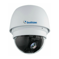
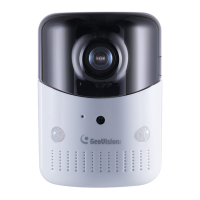
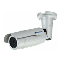
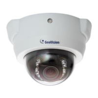
GeoVision GV Series Specifications

General IconGeneral
SeriesGV Series
CategorySecurity Camera
IP RatingIP66, IP67
Power SupplyPoE, 12V DC
Video CompressionH.264, H.265
Day/Night ModeYes
Network InterfaceRJ45
ResolutionVaries by model (e.g., 1080p, 4K)
LensVaries by model (e.g., fixed, varifocal)
IR DistanceVaries by model (e.g., 30m, 50m)

Related product manuals