30
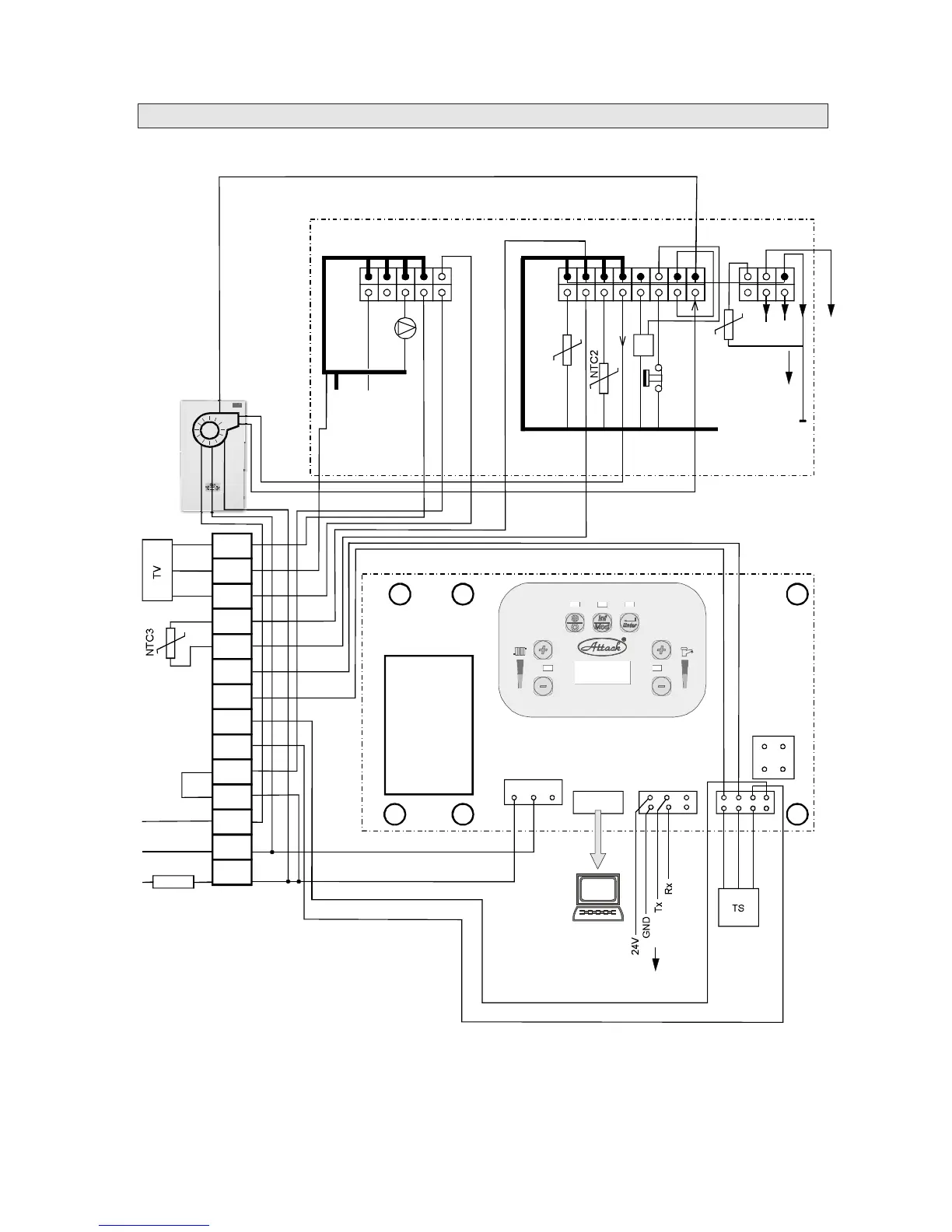
ChartofATTACKKSTwiring
X1X12X11
N L
GND
X4
MMI
Rx
HL
1
4
3
6
1
9
8
16
1
6
5
10
P
CVBC
MMIDISPLAY
GND
PWM
TACHO
X1
X5X4
X2
X3
N
FS
24V
Trafo
L
X11
CVBC
T2
T1
PE
N
L
S4
S3
OT2
OT1
S2
L
N
R
PE
N
L
L
N
PE
230V/50Hz
2A
THERMOSTAT
JUMPER
FAN
NTC1
GND
Tx
S1
PC
SP
GND
HL-emergencythermostat
FS-fluesensor
NTC1-Sensoroutletheatingwater
NTC2-Sensorreturnheatingwater
P-circulationpump
Fan
TS-pressuresensor
S1,S2-contactsofoutsidethermalsensor
OT1,OT2-contactsoftheOPENTHERMregulator
S3,S4-thermalsensorofhotwater
L,N,R-contactsofthree-wayvalveofhotwater230V
NTC3-sensoroftemperatureofhotwater
TV-driveofthethree-wayvalve
SP-sensorofhotwaterpassage