7
Installation
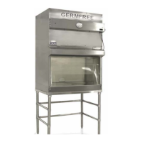
The BENCHTOP BIOFLOW CHAMBER is ordinarily transported and moved in the upright
position. The exhaust filter of the BENCHTOP BIOFLOW CHAMBER is located within the unit
and the dimensions are such that it will fit through any opening 32” wide and 58” high. If narrower
doors are encountered, the light housing can be taken off by removing four screws or the viewing
panel with the attached light housing can be completely removed by sliding the split hinges to the
right. This will reduce the width of the BIOFLOW CHAMBER to 28”. An additional 3/4”
clearance is required for the two clamps located level with the bottom of the viewing panel.
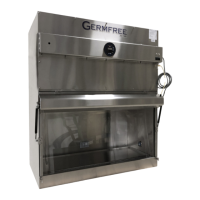
Services
The BENCHTOP BIOFLOW CHAMBER operates on an 115v, 1-phase, 60 Hertz, 10 Amp
electrical system. During shipment, the power cord is coiled within the control panel. The plug of
the power cord is a 3-pronged safety type and should be put into the appropriate 3-prong 115v
receptacle. For convenience of operations and service, all circuitry is located within the control
panel.
Standard services include the Motor ON/OFF switch, light switch, a magnehelic gauge at the front
of the unit and a speed control located in the control panel behind a plastic cap. Optional duplex
electric outlets may be located in the rear of the work area and optional stopcocks may be placed at
either side at the front of the unit, according to your specifications.