18
19
RENTAL SERIES
ELECTRICAL GENERATOR
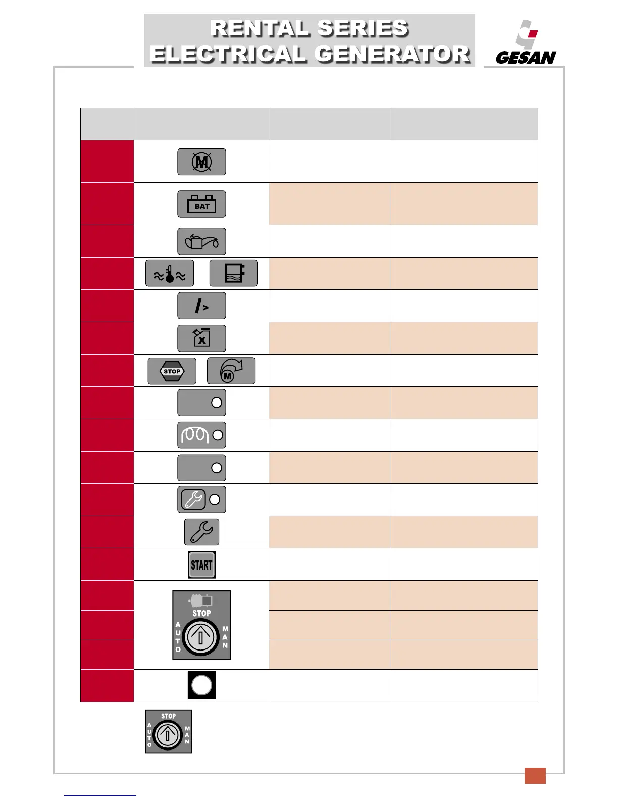
NUMBER SYMBOL DESCRIPTION IDENTIFICATION
1
Unit startup failure /
alternator failure.
Flashing red light: three failed startup
attempts
.
Continuous red light: voltage failure
or low frequency.
2
Battery charge alternator
failure.
Flashing red light: battery charge
alternator failure .
Continuous red light (unit stopped):
indicates contact.
3
Low oil level.
Flashing red light: low oil level.
Continuous red light (unit stopped):
indicates contact.
4
Low level / high coolant
temperature.
Flashing red light: high temperature.
Continuous red light: low coolant level
.
5
Overload. Flashing red light: unit overload.
6
Low fuel level.
Red: low fuel level.
(Continuous/flashing red light:
stopped/warning)
.
7
Emergency stop / overspeed
.
Flashing red light: emergency stop.
Continuous red light: engine
overspeed.
8
Remote startup mode.
Green LED.
9
Unit heating.
Yellow LED.
10
Stop signal.
F
lashing red light: imminent stoppage.
Continuous red light: stop command.
11
Maintenance signal.
F
lashing blue: see maintenance
section.
12
Maintenance reset button
.
Button.
13
Unit startup button. Button.
14
Manual mode. MAN
15
Key position for stopping
unit.
STOP
16
Automatic mode. AUTO
17
Programmable alarm.
Flashing or continuous red light;
user-defined.
AUTO
TEST
STOP
Fuel
T
he GPM-2 control module has three positions: STOP, automatic (AUTO) and manual
(
MAN). Key selectable (numbers 14 through 16 of the descriptive chart for the control
module).