11
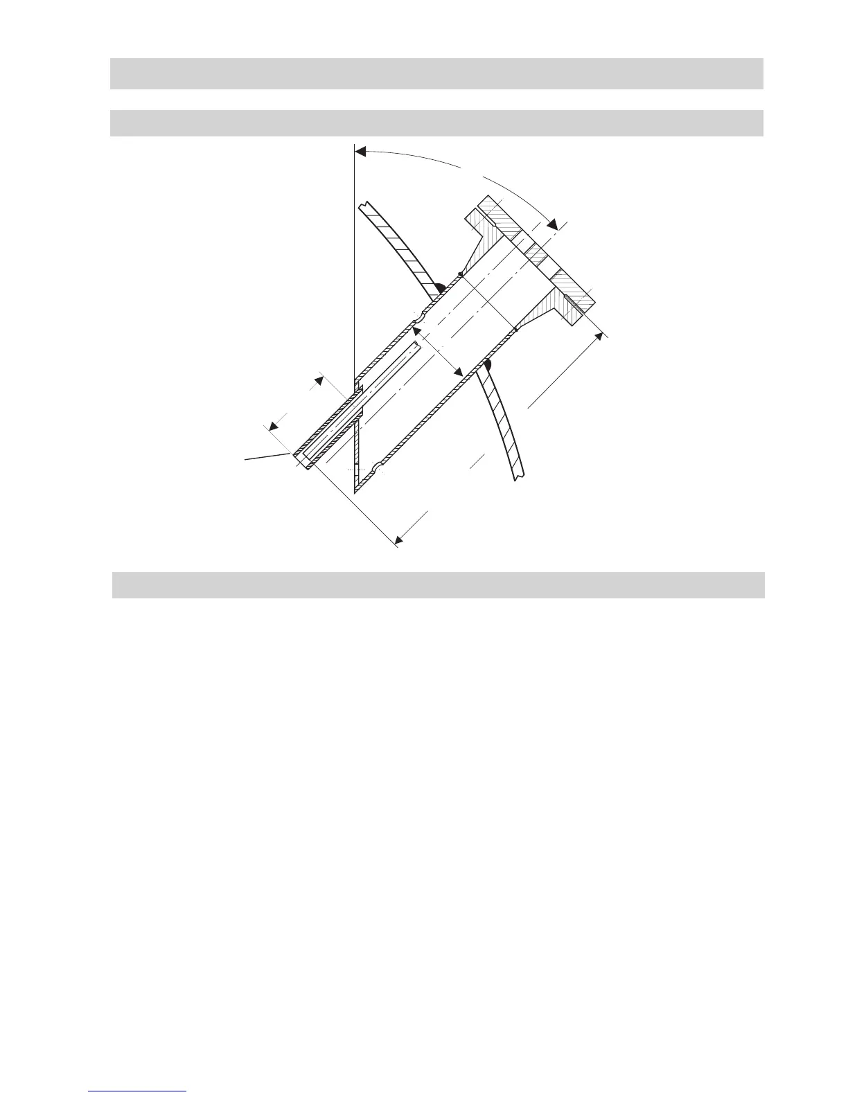
Examples of installation
6 Flange PN 40, DN 50, DIN EN 1092-01 (single electrode)
Flange PN 40, DN 100, DIN EN 1092-01 (combination of electrodes)
7 For the approval of the boiler standpipe with connecting flange the relevant regulations must be
considered.
8 Vent hole ∅ 20 mm
9 High water (HW)
0 Electrode tip
a Protection tube DN 80 (in France according to AFAQ ≥ DN 100)
b Protection tube DN 100
c Distance between electrode rod and protection tube ≥ 14 mm
d Distance between electrode tip (NRG 1..-50 or NRG 1...-51) ≥ 14 mm
(creepage distances and clearances)
e Low water LW
f Reducer DIN 2616-2, K-88.9 x 3.2-42.4 x 2.6 W
f Reducer DIN 2616-2, K-114.3 x 3.6-48.3 x 2.9 W
h Level pot ≥ DN 80
Key
- continued -
DN 100
45°
max.688
8
Tube, e. g. 33.7 x 3.2
8
8
120
Fig. 8 Inclined installation
e. g. in steam boilers
6
NRG 26-21
- continued -