13
Electrical connection
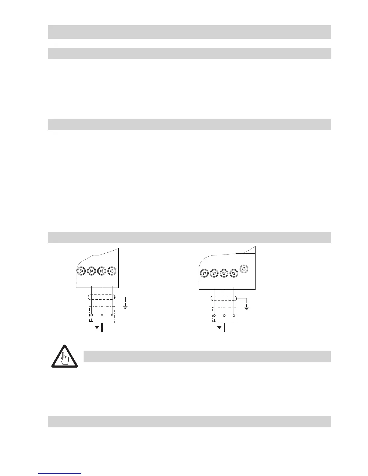
Connection of level electrode
To connect the equipment use screened multi-core control cable with a min. conductor size 0.5 mm²,
e. g. LiYCY 4 x 0.5 mm², max. length 100 m.
A maximum of 3 switches / controllers NRS /NRR 2-5.. can be connected to one level electrode.
Connect the screen only once to the central earthing point (CEP) in the control cabinet. Wire terminal
strip in accordance with the wiring diagram. Fig. 9
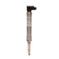
NRV 2-29, connecting the terminal strip
1. Loosen screw i. Fig. 9
2. Detach terminal box (electronic module NRV 2-29) o from level electrode. Leave sealing plate n
on contact plate.
3. Remove cover j and seal k.
4. Unscrew cable gland m.
5. Pull cable through cable gland m in terminal box o and wire terminals l in accordance with wiring
diagram Fig. 9.
6. Replace cover j and insert screw i.
7. Put terminal box o onto level electrode and fix it with screw i.
Wiring diagram
Please observe the instructions given in the installation & operating manual for the
level switches / controllers NRS 2-50, NRS 2-51, NRR 2-50, NRR 2-51, NRR 2-52 and
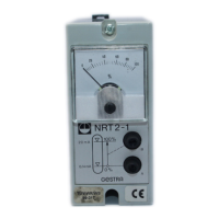
NRR 2-53 or NRS 2-1, NRR 2-1, NRR 2-2 and NRT 2-1!
Make sure that connecting cables leading to the level electrode are segregated and
run separately from power cables .
Attention
Tools
Screwdriver, size 1
Screwdriver, size 2.5, completely insulated according to DIN VDE 0680-1
5678
13
+12V
CEP
NRG 26-21
NRS 2-50, NRS 2-51
NRR 2-50, NRR 2-51
12 13 14 15
13
+12V
CEP
NRS 2-52, NRS 2-53
NRG 26-21
- continued -
Fig. 10 Fig. 11