32
NRR 240
Operation
Normal operation, controller is working.
The green LEDs 2 and 3 are flashing when the
external control valve is being opened or closed.
All LEDs go out once the setpoint is reached.
The LED “Power” is illuminated.
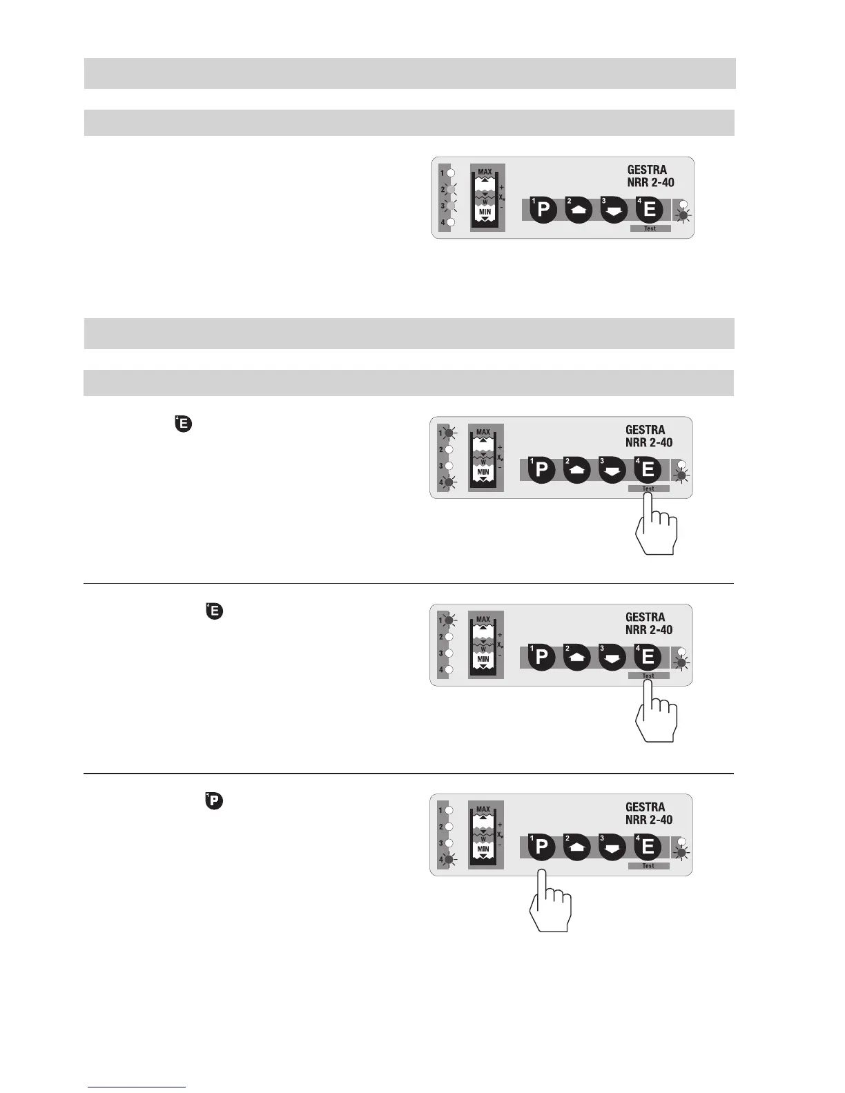
Test
NRR 240
Hold down button .
LED 4 goes out.
A MIN alarm is simulated for
switchpoint 4.
Press button
briefly.
The test mode (relay test) remains active for 5
seconds.
Hold down button .
LED 1 goes out.
A MAX alarm is simulated for
switchpoint 1.
 Loading...


