4
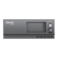
I/O Options
The actual connectors you have depend on the model purchased.
No. Name Description
Audio in connector
(BNC female)
To connect to a camera with analog (CVBS) output.
Video in connector
(BNC female)
To connect to a camera with analog (CVBS) output.
3
. References
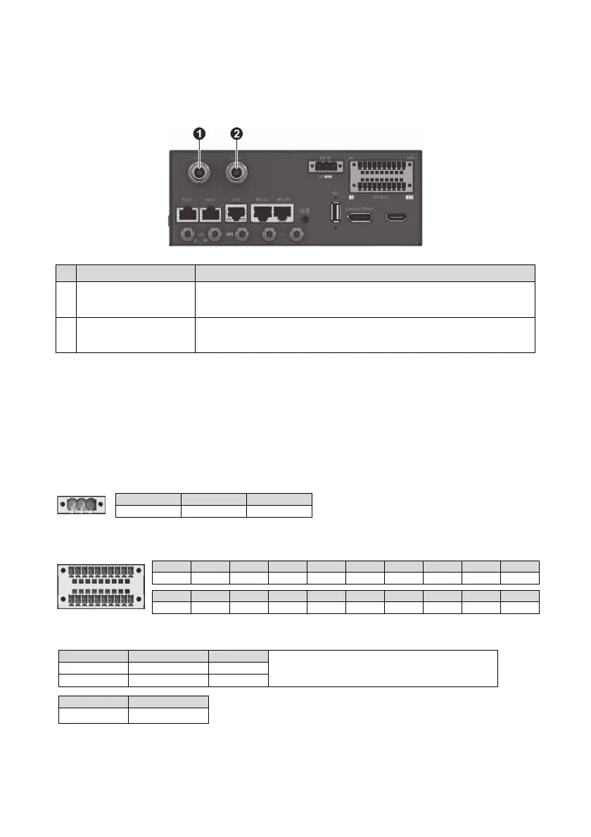
Pin Assignments
DC-in Connector Pin Assignments
GPIO Connector Pin Assignments
Notes on GPIO:
More Information
See Installation Diagram for more information.
A1 A10
B1 B10
A1 A2 A3 A4 A5 A6 A7 A8 A9
A10
GND +12V GND GND I/O Out 4 I/O Out 3 I/O In 8 I/O In 7 I/O In 6
I/O In 5
B1 B2 B3 B4 B5 B6 B7 B8 B9 B10
GND +12V GND GND I/O Out 2 I/O Out 1 I/O In 4 I/O In 3 I/O In 2 I/O In 1
1 2 3
Ignition Vehicle Battery+ GND
Pins Low / High Active Input Voltage
When using a digital I/O device, you must ground the
device by connecting it to the metal part of the VR-X20
cabinet. This common return path is needed as the
reference point for high/low voltage measurement.
I/O In 1, 2, 5, 6 Low Active 0 V
I/O In 3, 4, 7, 8 High Active 6 V~24 V
Pins Output Voltage
I/O Out 1, 2, 3, 4
12V
123