4
Installation instructions
5018606-00 Rev.C Edition 0704
Bottom frame
V318
Foot plate
Installation
• The floor where the machine is to stand must be flat and level within ±5 mm.
• Pull the machine (on a transport pallet) to the location where it will be installed.
• Lift the machine off the pallet.
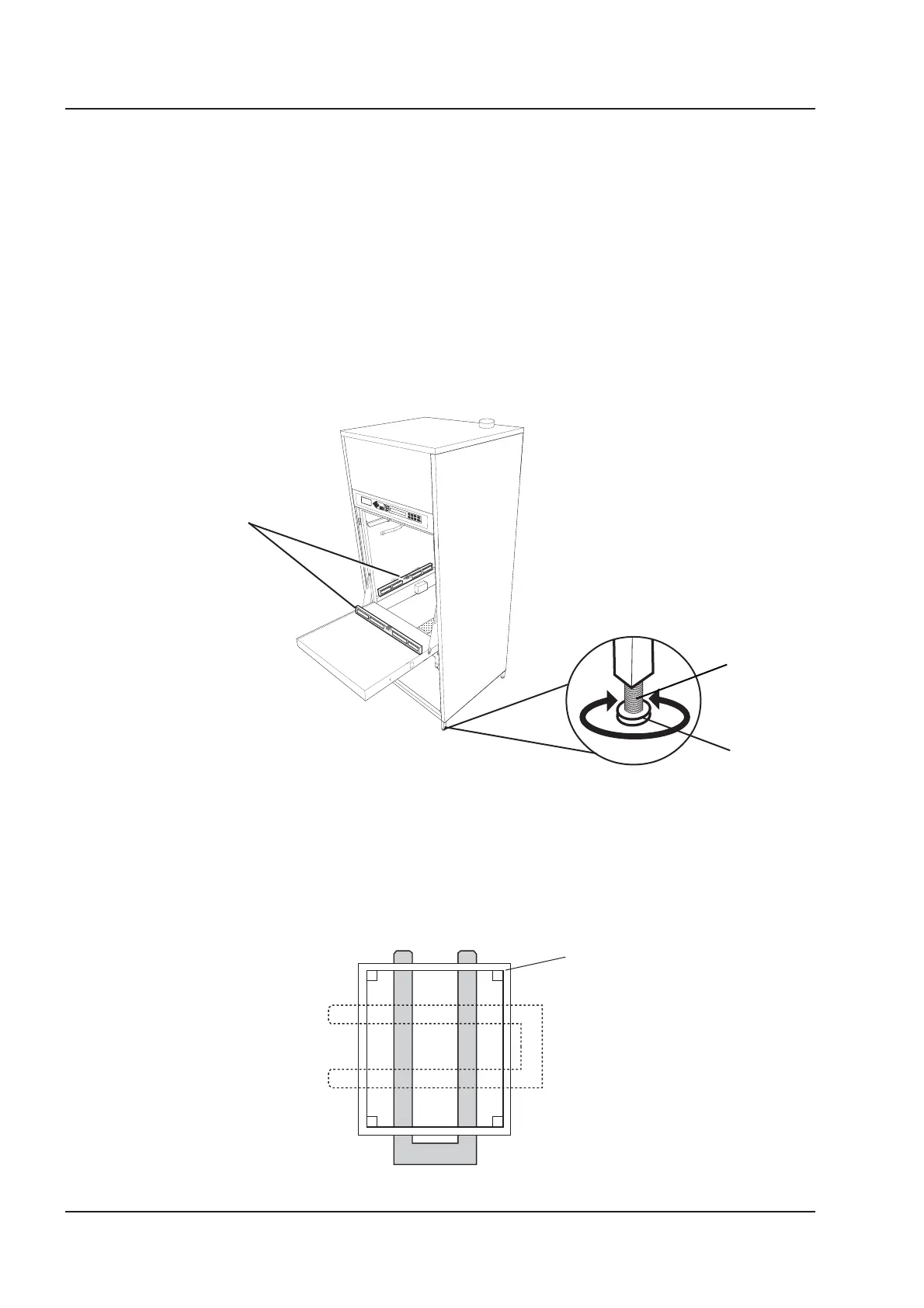
• Position the machine at the chosen location and adjust the feet so that the
machine is stable. The adjusting feet must be screwed out not more than
110 mm from the underside of the machine (the 100 mm dimension on Figure 3
can be ±10 mm). There must be clear space for loading/unloading the machine
1700 mm in front of the door(s) of the machine.
• Place a foot plate under each adjusting screw. Foot plates are supplied in a
plastic bags in the chamber of the machine.
V1634
Adjusting screws
Figure 1. Adjustment
• Using a spirit level, check as shown in Figure 1 that the machine is level within ±2 mm,
• Free-standing model: prepare a water supply and a waste connection by breaking
out suitable prepared openings in the rear cover plate panel of the machine.
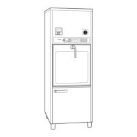
• If the machine is to be moved with a pallet truck, the forks of the pallet truck
must be positioned as shown in Figure 2 to avoid damage to the machine.
Figure 2. Positioning the pallet truck forks.
Installation
Level the machine
with a spirit level.