The GGM GUF Series BLDC Speed Control Unit is a sophisticated device designed for precise control of Brushless DC (BLDC) motors, offering stable and wide-ranging speed regulation for various industrial applications. This operation manual provides comprehensive details on its features, specifications, and usage, ensuring proper installation, operation, and maintenance.
Function Description:
The GUF Series BLDC Speed Control Unit acts as an interface between an AC power supply and a BLDC motor, enabling users to control motor speed, direction, and operational parameters. It employs vector control to maintain stable rotation speed, even under varying load conditions, by constantly comparing the set speed with the motor's speed feedback signal.
Key functions include:
- Stable Speed Control: Achieves a speed ripple of 0.5% or less, ensuring consistent motor performance across a wide range of speeds (100 to 4000 r/min). This is facilitated by vector control, which dynamically adjusts the current applied to the motor based on real-time speed feedback.
- Wide Speed Control Range: Supports motor speeds from 100 to 4000 r/min, making it suitable for applications requiring both low and high-speed operations.
- Simple Connection: Designed for ease of installation, featuring simple motor connector wiring and screw-type terminals for power and I/O connections.
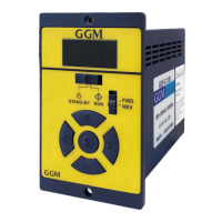
- User-Friendly Front Panel Operation: The front panel includes an operation switch (STAND-BY/RUN), rotational direction switch (FWD/REV), and setting buttons (+/-/S) for intuitive control of the motor.
- External I/O Operation (PLC, etc.): Allows for start/stop, rotational direction changes, and multi-level speed operation via external I/O signals, integrating seamlessly with Programmable Logic Controllers (PLCs) and other control systems.
- Display Indication: Features a digital display that shows load ratio (0-100%) and actual speed (0-4000 rpm), providing real-time operational feedback.
- Multi-level Speed Operation (8 Speeds): Supports up to 8 distinct speed settings, configurable through operation data numbers (0-7), enabling flexible application control.
- Setting/Operation Lock: A lock function prevents accidental changes to speed or data settings, enhancing operational safety. This can be activated or deactivated by pressing and holding the 'S' button for 5 seconds in STAND-BY mode.
- Protection Function: Incorporates safety features to detect abnormal statuses such as overload and overvoltage. In case of an abnormality, the unit stops operation and triggers an alarm.
Important Technical Specifications:
The GUF Series is available in various models, including GUF-C-30, GUF-C-60, GUF-C-150, GUF-C-200, and GUF-C-400, corresponding to rated output powers of 30W, 60W, 150W, 200W, and 400W, respectively.
- Rated Output Power (Continuous): Ranges from 30W to 400W.
- Rated Voltage: Single-phase 200~240V (permissible range ±10%) or Three-phase 200~240V (permissible range ±10%).
- Rated Frequency: 50/60 Hz (permissible range ±5%).
- Rated Input Current: Varies by model, e.g., GUF-C-30: Single-Phase 0.8A, Three-Phase 0.5A; GUF-C-400: Single-Phase 4.0A, Three-Phase 3.0A.
- Maximum Input Current: Varies by model, e.g., GUF-C-30: Single-Phase 1.9A, Three-Phase 1.1A; GUF-C-400: Single-Phase 7.8A, Three-Phase 5.0A.
- Rated Output Current: Ranges from 0.17A (GUF-C-30) to 2.30A (GUF-C-400).
- Rated Torque: Ranges from 0.1 N.m (GUF-C-30) to 1.3 N.m (GUF-C-400).
- Maximum Instantaneous Torque: Ranges from 0.15 N.m (GUF-C-30) to 1.80 N.m (GUF-C-400).
- Rated Speed: 3000 r/min.
- Speed Control Range: 100~4000 r/min.
- Speed Regulation: 0.5% or less (under specified conditions).
- Operating Temperature: 0~40℃ (Non-freezing).
- Storage Temperature: -20~70℃ (Non-freezing).
- Operating Humidity: 85% below (Non-condensing).
- Storage Humidity: 85% below (Non-condensing).
- Environment: Free from corrosive gas, dust, and splashing water/oil.
- Input Signal: 5 user inputs (Photocoupler).
- Output Signal: 3 user outputs (Photocoupler).
- Dimensions:
- 30, 60, 150W drives: 58mm (W) x 90mm (H) x 98mm (D) with a 116mm overall depth including mounting brackets.
- 200, 400W drives: 64.5mm (W) x 115mm (H) x 124mm (D) with a 125mm overall depth including mounting brackets.
Usage Features:
- Operation Switch: Toggling to "RUN" starts the motor, while "STAND-BY" stops it.
- Speed Adjustment: Pressing the "+" button increases speed by 1 r/min, and "-" decreases it by 1 r/min. Holding these buttons accelerates/decelerates by 10 r/min or 100 r/min increments.
- Rotation Speed Confirmation and Lock: Pressing the "S" button confirms the set speed. Holding "S" for 5 seconds in STAND-BY mode locks the operation, preventing speed changes.
- Rotational Direction Control: The FWD/REV switch changes the motor's rotation direction, even during operation.
- External Input Function Setting: Parameters can be configured to enable or disable external I/O control.
- Multi-Speed Operation: By combining ON/OFF states of P0, P1, and P2 inputs, users can select from 8 predefined operation data numbers, each with its own rotation speed, acceleration/deceleration time, and torque limit.
- Alarm and Warning Displays: The unit provides clear indications for various alarms (e.g., overload, overvoltage, sensor error) and warnings, aiding in quick troubleshooting.
- Parameter Setting: A comprehensive parameter menu allows users to fine-tune acceleration/deceleration times, torque limits, overload alarm detection times, speed upper/lower limits, and speed reduction/increasing ratios.
- Initialization: The parameter mode can be initialized to factory settings.
Maintenance Features:
- Safety Precautions: The manual emphasizes critical safety measures, including avoiding use near explosive/flammable materials, not bending/pulling motor wires, ensuring power is off during installation/inspection, and having qualified personnel perform work.
- Alarm List: A detailed alarm list provides alarm codes, types, causes, and remedial actions for common issues like undervoltage, overvoltage, overheat, overcurrent, speed feedback error, sensor error, overspeed, overload, and external errors.
- Troubleshooting: The alarm list serves as a valuable resource for diagnosing and resolving operational problems, guiding users to check power supply, wiring, load, and environmental conditions.
- Parameter Saving: The "Stor" mode allows users to save current parameter settings to non-volatile memory (NVM), ensuring settings are retained even after power cycles.
- Developer Setting: An access level setting (0-User setting) is available, likely for advanced configuration or diagnostic purposes.
- Overload Protection: The unit features an overload alarm detection time parameter (oL.tM) to prevent motor damage under sustained overload conditions. However, it warns that prolonged overload, even within the limited duty region, can shorten the service life of the motor and gearhead.
- Wiring Guidelines: Provides specifications for applicable lead wires (AWG 18~14 for power, AWG 26~20 for I/O) and recommends using restoration resistance for short reduction times or large inertias.
- Technical Support: Users are encouraged to contact their vendor or the second factory for any product-related questions or post-sales service.