9) BAT (Battery)
Thebatteryprovidespowertokeepthevalues(suchasBIOScongurations,date,andtimeinformation)
intheCMOSwhenthecomputeristurnedoff.Replacethebatterywhenthebatteryvoltagedropstoalow
level, or the CMOS values may not be accurate or may be lost.
You may clear the CMOS values by removing the battery:
1. Turn off your computer and unplug the power cord.
2. Gently remove the battery from the battery holder and wait for one minute. (Or
use a metal object like a screwdriver to touch the positive and negative terminals
of the battery holder, making them short for 5 seconds.)
3. Replacethebattery.
4. Plug in the power cord and restart your computer.
• Always turn off your computer and unplug the power cord before replacing the battery.
• Replacethebatterywithanequivalentone.Dangerofexplosionifthebatteryisreplacedwith
an incorrect model.
• Contact the place of purchase or local dealer if you are not able to replace the battery by yourself
or uncertain about the battery model.
• When installing the battery, note the orientation of the positive side (+) and the negative side (-)
of the battery (the positive side should face up).
• Used batteries must be handled in accordance with local environmental regulations.
The front panel design may differ by chassis. A front panel module mainly consists of power switch,
reset switch, power LED, hard drive activity LED, speaker and etc. When connecting your chassis
front panel module to this header, make sure the wire assignments and the pin assignments are
matched correctly.
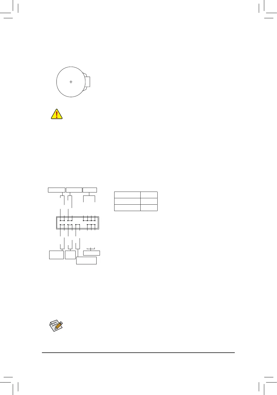
10) F_PANEL(FrontPanelHeader)
Connect the power switch, reset switch, speaker, chassis intrusion switch/sensor and system status indicator
on the chassis to this header according to the pin assignments below. Note the positive and negative pins
before connecting the cables.
System Status LED
S0 On
S3/S4/S5 Off
• PW(PowerSwitch,Red):
Connects to the power switch on the chassis front panel. You may
congurethewaytoturnoffyoursystemusingthepowerswitch(refer
to Chapter 2, "BIOS Setup," "Power," for more information).
• SPEAK(Speaker, Orange):
Connects to the speaker on the chassis front panel. The system reports
system startup status by issuing a beep code. One single short beep
will be heard if no problem is detected at system startup.
• PLED/PWR_LED(Power LED, Yellow/Purple):
Connects to the power status indicator
on the chassis front panel. The LED is on
when the system is operating. The LED is
off when the system is in S3/S4 sleep state
or powered off (S5).
• HD (Hard Drive Activity LED, Blue):
Connects to the hard drive activity LED on the chassis front panel. The LED is on when the hard drive is
reading or writing data.
• RES(ResetSwitch,Green):
Connects to the reset switch on the chassis front panel. Press the reset switch to restart the computer if the
computer freezes and fails to perform a normal restart.
• CI (Chassis Intrusion Header, Gray):
Connects to the chassis intrusion switch/sensor on the chassis that can detect if the chassis cover has been
removed. This function requires a chassis with a chassis intrusion switch/sensor.
• NC (Orange): No Connection.
Power LED
1
2
19
20
CI-
CI+
PWR_LED-
PWR_LED+
PLED-
PW-
SPEAK+
SPEAK-
PLED+
PW+
Power LED
HD-
RES+
HD+
RES-
Hard Drive
Activity LED
Reset
Switch
Chassis Intrusion
Header
Power Switch Speaker
PWR_LED-
NC
NC
- 16 -
 Loading...