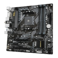
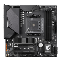
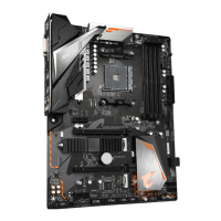
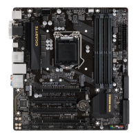
Installation Notices for the M.2 and SATA Connectors:
Due to the limited number of lanes provided by the Chipset, the availability of the SATA connectors may be
affectedbythetypeofdeviceinstalledintheM2A_32Gconnector.TheM2A_32Gconnectorsharesbandwidth
withtheSATA30connector.Refertothefollowingtablefordetails.
The front panel design may differ by chassis. A front panel module mainly consists of power switch, reset
switch, power LED, hard drive activity LED, speaker and etc. When connecting your chassis front panel
module to this header, make sure the wire assignments and the pin assignments are matched correctly.
8) F_PANEL (Front Panel Header)
Connect the power switch, reset switch, speaker, chassis intrusion switch/sensor and system status indicator
onthechassistothisheaderaccordingtothepinassignmentsbelow.Notethepositiveandnegativepins
before connecting the cables.
System Status LED
S0 On
S3/S4/S5 Off
• PW(PowerSwitch,Red):
Connects to the power switch on the chassis front panel. You may
congurethewaytoturnoffyoursystemusingthepowerswitch(refer
toChapter2,"BIOSSetup,""Power,"formoreinformation).
• SPEAK (Speaker, Orange):
Connects to the speaker on the chassis front panel. The system reports
system startup status by issuing a beep code. One single short beep
will be heard if no problem is detected at system startup.
• PLED/PWR_LED (Power LED, Yellow/Purple):
Connects to the power status indicator
on the chassis front panel. The LED is on
when the system is operating. The LED is
off when the system is in S3/S4 sleep state
or powered off (S5).
• HD (Hard Drive Activity LED, Blue):
Connects to the hard drive activity LED on the chassis front panel. The LED is on when the hard drive is
reading or writing data.
• RES (ResetSwitch,Green):
Connects to the reset switch on the chassis front panel. Press the reset switch to restart the computer if the
computer freezes and fails to perform a normal restart.
• CI (Chassis Intrusion Header, Gray):
Connects to the chassis intrusion switch/sensor on the chassis that can detect if the chassis cover has been
removed. This function requires a chassis with a chassis intrusion switch/sensor.
• NC (Orange):NoConnection.
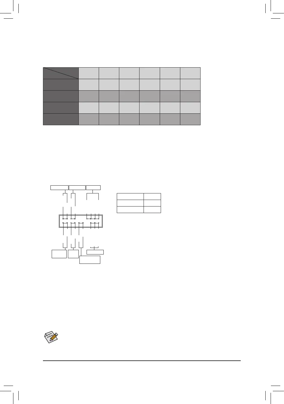
SATA3 0 SATA3 1 SATA3 2 SATA3 3 SATA3 4 SATA3 5
M.2 SATA SSD
r a a a a a
M.2 PCIe x4 SSD
a a a a a a
M.2 PCIe x2 SSD
a a a a a a
NoM.2SSDsInstalled
a a a a a a
a: Available, r:Notavailable.
Connector
Type of M.2
SSD Installed
Power LED
1
2
19
20
CI-
CI+
PWR_LED-
PWR_LED+
PLED-
PW-
SPEAK+
SPEAK-
PLED+
PW+
Power LED
HD-
RES+
HD+
RES-
Hard Drive
Activity LED
Reset
Switch
Chassis Intrusion
Header
Power Switch
Speaker
PWR_LED-
NC
NC
- 15 -
 Loading...