5) SYS_FAN3_PUMP (System Fan/Water Cooling Pump Header)
The fan/pump header is 4-pin and possesses a foolproof insertion design. Most fan headers possess a
foolproof insertion design. When connecting a fan cable, be sure to connect it in the correct orientation (the
black connector wire is the ground wire). The speed control function requires the use of a fan with fan speed
control design. For optimum heat dissipation, it is recommended that a system fan be installed inside the
chassis.Theheaderalsoprovidesspeedcontrolforawatercoolingpump,refertoChapter2,"BIOSSetup,"
"M.I.T.,"formoreinformation
6) CPU_OPT (Water Cooling CPU Fan Header)
The fan header is 4-pin and possesses a foolproof insertion design. Most fan headers possess a foolproof
insertion design. When connecting a fan cable, be sure to connect it in the correct orientation (the black
connector wire is the ground wire). The speed control function requires the use of a fan with fan speed control
design.
1
1
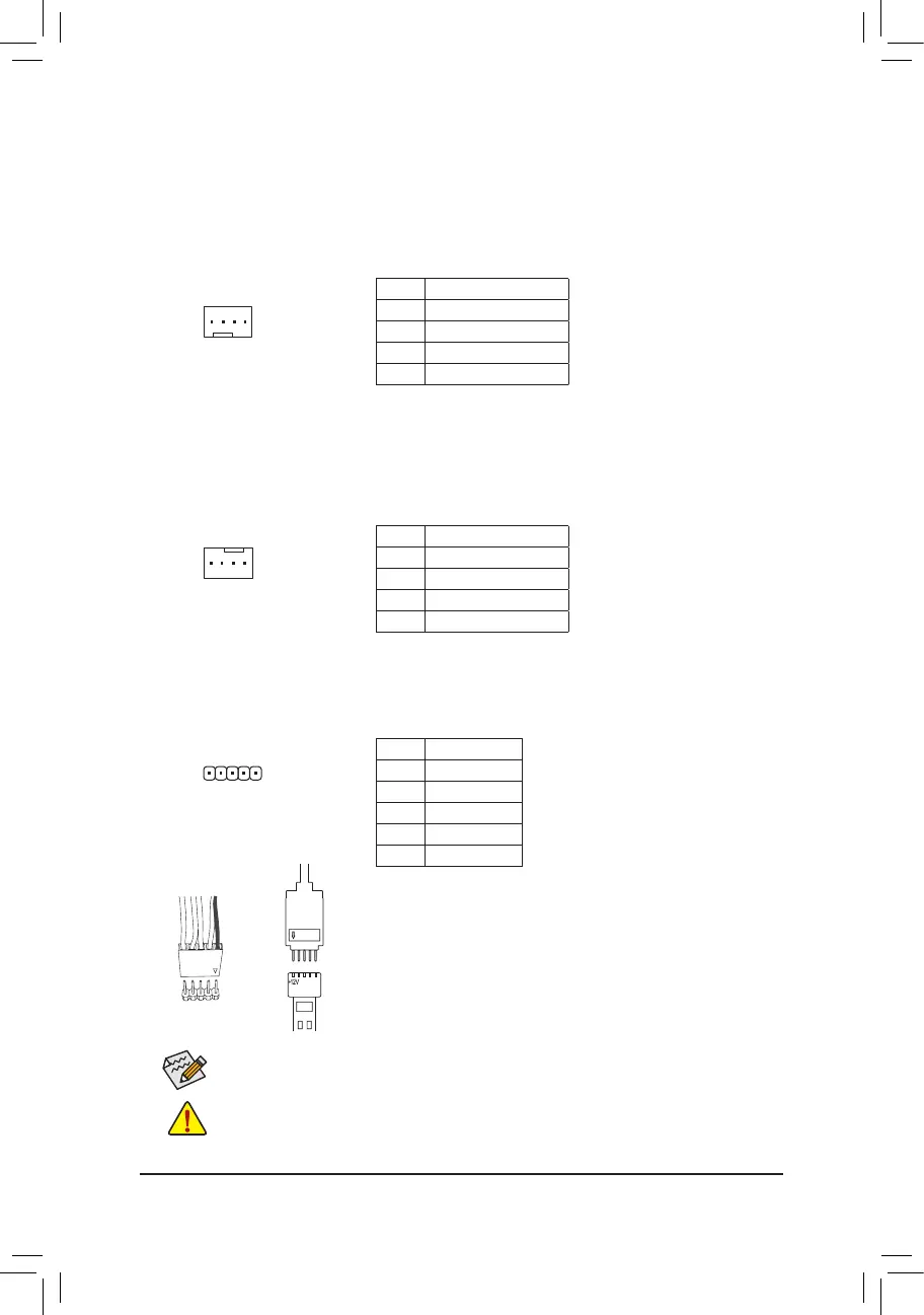
7) LED_C (RGB (RGBW) LED Strip Extension Cable Header)
Theheadercanbeusedtoconnectastandard5050RGB(RGBW)LEDstrip(12V/G/R/B/W),withmaximum
power rating of 2A (12V) and maximum length of 2m.
Pin No. Denition
1 12V
2 G
3 R
4 B
5 W
Before installing the devices, be sure to turn off the devices and your computer. Unplug the power
cord from the power outlet to prevent damage to the devices.
Forhowtoturnon/offthelightsoftheRGB(RGBW)LEDstrip,refertotheinstructionsinChapter2,
"BIOSSetup."
ConnectoneendoftheRGB(RGBW)LEDstripextensioncabletotheheader
andtheotherendtoyourRGB(RGBW)LEDstrip.Theblackwire(marked
with a triangle on the plug) of the extension cable must be connected to Pin
1 (12V) of this header. The 12V pin (marked with an arrow) on the other end
of the extension cable must be lined up with the 12V of the LED strip. Be
careful with the connection orientation of the LED strip; incorrect connection
may lead to the damage of the LED strip.
12V
1
Black wire
12V of the
LED strip
F_USB30
F_U
B_
F_ F_
_
B
BS_
B
SB_
B
_S
S_
_
B
_U
_
B
S
123
123
123
123
1
1
1
1
BSS
S
_S
SSU
1 2 3 4 5
S3
BSSS
U
__ 3
F_USB3F
S _
S _
S _
SF
B_
B_
F
_0
S
S
_0F
_F
_
_
__B
U
S _S
_
USB0_B
B_
1
Pin No. Denition
1 GND
2 Voltage Speed Control
3 Sense
4 PWM Speed Control
Pin No. Denition
1 GND
2 Voltage Speed Control
3 Sense
4 PWM Speed Control
- 16 -
 Loading...