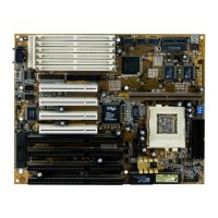
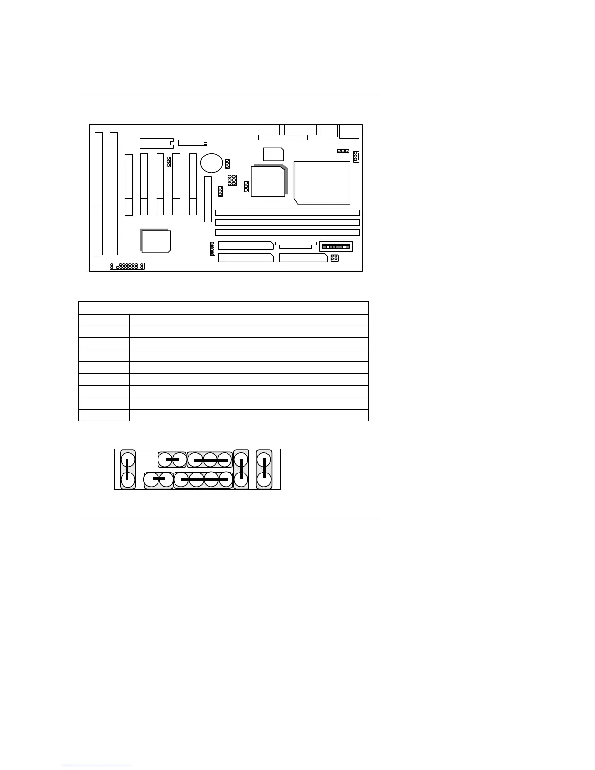
EasyManua.ls Logo

Gigabyte 5AX - Mainboard Layout; Quick Reference for Jumpers & Connectors

Gigabyte 5AX
97 pages
To Next Page IconTo Next Page
To Previous Page IconTo Previous Page
Loading...
Hardware Installtion
3-2
3.2. MAINBOARD LAYOUT
CPU
JP5
SW
JP3
1
BANK 0
BANK 2
BANK 1
IDE 2
IDE 1
FLOPPY
LPT
COM A
PS/2
USB COM B
PCI 1 PCI 2 PCI 3 PCI 4
SL 3 SL 5
SL 4 SL 6
ATX POWER
AGP
FAN
PWR
JP8
JP7
JP9
1 1
M1541
M1543C
BAT1
5AX
JP10
BIOS
PCI 5
JP13
JP11
IR
JP6
×Figure 3.1Ø
3.3. QUICK REFERENCE FOR JUMPERS & CONNECTORS
t I/O Port Connectors
IDE 1 For Primary IDE port.
IDE 2 For Secondary IDE port.
FLOPPY For Floppy port.
USB For USB port.
COM B For Serial port2 (COM B){Support Modem Ring On}.
COM A For Serial port1 (COM A){Support Modem Ring On}.
LPT For LPT port.
PS/2 For PS/2 Mouse & Keyboard Connector.
ATX PWR For ATX Power Connector.
JP6 : 2*11 PIN Jumper
PWR
P+P
P
HD
RES SPK
JP6
1 1
1
GN GD

Related product manuals