- 8 -
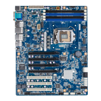
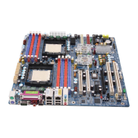
37 USB_A USB Type A connector
38 BP_1 Back plane board header
39 SAS0/1/2/3 SAS 3Gb/s connectors
40 BIOS_RCVR BIOS Recovery jumper
41 F_USB3_1 USB 3.0 header
42 F_USB_1 USB 2.0 header
43 SAS_SGPIO SAS SGPIO header
44 BIOS_WP BIOS Write Protect jumper
45 BMC_FRB1 Force to Stop FRB3 Timer jumper
46 TPM TPM module connector
47 COM2 Serial port cable header
48 PCI_1 PCI 32bit/33MHz slot
49 PCIE1
PCI-E x16 slot (Shared badwidth with
PCIE3 slot)
50 PCIE2 PCI-E x1 slot
51 PCIE3 PCI-E x16 slot (Shared badwidth with
PCIE1 slot)
52 PCIE4 PCI-E slot
53 U393 BMC Upgrade ROM
54 U392 ASPEED AST2300 chipset
55 BMC_LED1 BMC readiness LED
56 SSB_ME1 ME Recovery jumper
57 U17 iTE IT8728F Super I/O
58 SYS_FAN4 System fan #4 connector
59 U430 Intel 82574L chipset
60 U15 EtronTech EJ188H chipset
61 U432 Intel 82574L chipset
62 U442 Intel 82574L chipset
63 U444 Intel 82574L chipset
CAUTION! If a SATA type hard drive is connected to the motherboard, please ensure the jumper is
closed and set to 2-3 pins (Normal mode), in order to reduce any risk of hard disk damage. Please
refer to Page 32 for SATA_DOM0 and SATA_DOM1 jumper setting instruction.

 Loading...

