7IXE4 Motherboard
15
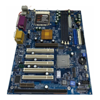
Panel And Jumper Definition
J22: For 2x11 Pins Jumper
RE
GN
GD
PW
P+P
−
P
−
S P K
HD
1
1
1
1
GN (Green Switch) Open: Normal Operation
Close: Entering Green Mode
GD (Green LED) Pin 1: LED anode(+)
Pin 2: LED cathode(
−
)
HD (IDE Hard Disk Active LED) Pin 1: LED anode(+)
Pin 2: LED cathode(
−
)
SPK (Speaker Connector) Pin 1: VCC(+)
Pin 2- Pin 3: NC
Pin 4: Data(
−
)
RE (Reset Switch) Open: Normal Operation
Close: Reset Hardware System
P+P
−
P
−
(Power LED)
Pin 1: LED anode(+)
Pin 2: LED cathode(
−
)
Pin 3: LED cathode(
−
)
PW (Soft Power Connector) Open: Normal Operation
Close: Power On/Off
 Loading...