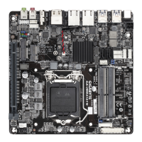
Internal
Connectors
1 x 4-pin ATX 12V power connector
1 x AT
/ATX mode switch jumper
1 x CPU fan header
1 x system fan header
1 x M.2 Socket 3 connector on the back of the motherboard
2 x SA
TA
6Gb/s connectors
1 x MSATA
connector
1 x USIM connector on the back of the motherboard
1 x SA
TA
power connector
1 x front panel header
1 x front panel audio header
1 x battery power cable connector
1 x USB 3.1 Gen 1 header
1 x USB 2.0/1.1 header
4 x serial port headers
4 x serial port power select jumpers
1 x D-Sub port header
1 x GPIO header
1 x LV
DS header
1 x LV
DS drive voltage jumper (LCD_VCC)
1 x
at panel display header (FPD)
1 x at panel display power select jumper (FPD_PWR)
1 x at panel display switch header (MON_SW)
1 x backlight switch header (BL_SW)
1 x speaker header (SPKR)
1 x buzzer header (SPEAKER)
1 x Clear CMOS jumper
1 x chassis intrusion header
1 x I2C
1 x SMBUS
Back Panel
Connectors
1 x DC-In power connector
1 x HDMI port
1 x DisplayPort
2 x USB 3.0 ports
2 x USB 2.0/1.1 ports
2 x RJ-45 ports
2 x audio jacks
I/O Controller iTE
®
I/O Controller Chip
Hardware
Monitor
System voltage detection
CPU/System temperature detection
CPU/System fan speed detection
CPU/System overheating warning
CPU/System fan fail warning
CPU/System fan speed control
* Whether the fan speed control function is supported will depend on the cooler you
install.
(Note) The connector is on the back of the motherboard.
- 7 -
 Loading...