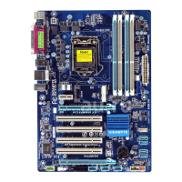
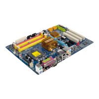
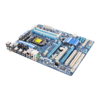
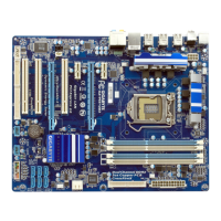
- 23 - Hardware Installation
A RAID 0 or RAID 1 conguration requires at least two hard drives. If more than two hard
•
drives are to be used, the total number of hard drives must be an even number.
A RAID 5 conguration requires at least three hard drives. (The total number of hard drives
•
does not have to be an even number.)
A RAID 10 conguration requires four hard drives.
•
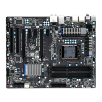
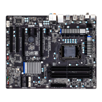
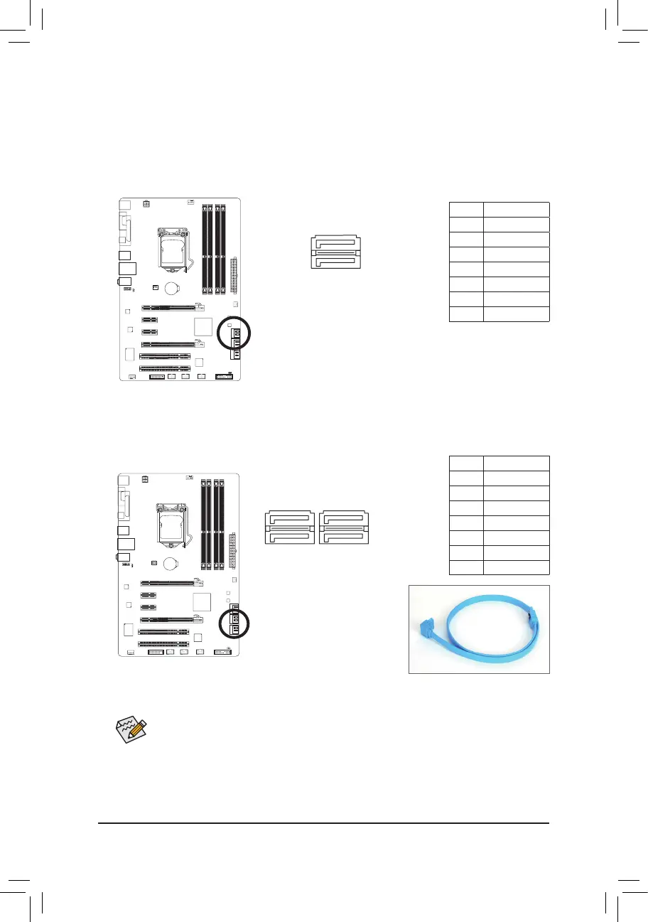
7) SATA3_0/1 (SATA 6Gb/s Connectors, Controlled by P67
j
/H67
k
Chipset)
The SATA connectors conform to SATA 6Gb/s standard and are compatible with SATA 3Gb/s and SATA
1.5Gb/s standard. Each SATA connector supports a single SATA device. The SATA3_0 and SATA3_1
connectors support RAID 0 and RAID 1. RAID 5 and RAID 10 can be implemented on the two connec-
tors with the SATA2_2/3/4/5 connector
(Note)
. Refer to Chapter 5, "Conguring SATA Hard Drive(s)," for
instructions on conguring a RAID array.
Please connect the L-shaped end of
the SATA cable to your SATA hard
drive.
8) SATA2_2/3/4/5 (SATA 3Gb/s Connectors, Controlled by P67
j
/H67
k
Chipset)
The SATA connectors conform to SATA 3Gb/s standard and are compatible with SATA 1.5Gb/s standard.
Each SATA connector supports a single SATA device. The P67
j
/H67
k
Chipset supports RAID 0,
RAID 1, RAID 5, and RAID 10. Refer to Chapter 5, "Conguring SATA Hard Drive(s)," for instructions on
conguring a RAID array.
(Note) When a RAID set is built across the SATA 6Gb/s and SATA 3Gb/s channels, the system perfor-
mance of the RAID set may vary depending on the devices being connected.
Pin No. Denition
1 GND
2 TXP
3 TXN
4 GND
5 RXN
6 RXP
7 GND
Pin No. Denition
1 GND
2 TXP
3 TXN
4 GND
5 RXN
6 RXP
7 GND
1
1
7
7
 Loading...