- 24 -
Hardware Installation
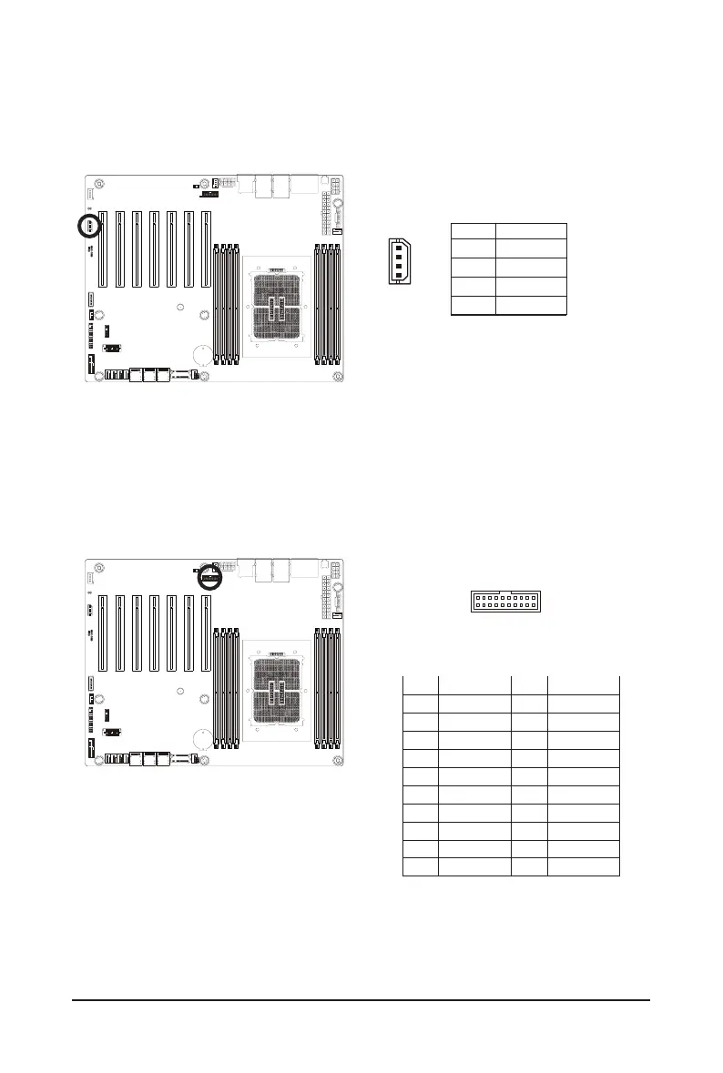
PinNo. Denition
1 Clock
2 Data
3 GND
4 VCC
13) IPMB (Intelligent Platform Management Bus) Connector
The Intelligent Platform Management Bus Communications Protocol defines a byte-level transport for
transferringIntelligentPlatformManagementInterfaceSpecication(IPMI)messagesbetweenintelligentI2C
devices.
4
1
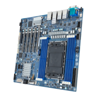
14) CN_NCSI (NCSI Connector)
Pin No. Denition Pin No. Denition
1 NCSI_CLK 2 GND
3 NCSI_RX_D0 4 GND
5 NCSI_RX_D1 6 GND
7 NCSI_CRS_DV 8 GND
9 NCSI_RX_ER 10 GND
11 P3V3_AUX 12 GND
13 NCSI_TX_D1 14 GND
15 NCSI_TX_D0 16 GND
17 NCSI_TX_EN 18 GND
19 NCSI_PRESENT 20 P3V3_AUX
19
20 2
1