- 11 - Hardware Installation
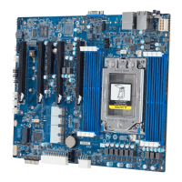
Internal I/O
Connectors
1 x 24-pin ATX main power connector
2 x 8-pin ATX 12V power connectors
4 x SlimSAS connectors
1 x M.2 slot
1 x CPU fan header
6 x System fan headers
1 x USB 3.0 header
2 x COM headers
1 x TPM header
1 x Front panel header
1 x HDD back plane board header
1 x PMBus connector
1 x IPMB connector
1xClearCMOSjumper
1xBIOSrecoveryjumper
Rear I/O
Connectors
2 x USB 3.0
1 x VGA
4 x RJ45 (MZ01-CE0), 2 x RJ45 (MZ01-CE1)
1 x MLAN
1 x ID switch with LED
1 x Power switch with LED
TPM
1 x TPM header with LPC interface
Optional TPM2.0 kit: CTM000
Board
Management
Aspeed® AST2500 management controller
GIGABYTE Management Console (AMI MegaRAC SP-X) web interface
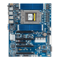
Form Factor
ATX
305W x 244D (mm)
GIGABYTE reserves the right to make any changes tothe product specications and product-related
information without prior notice.
 Loading...