Hardware Installation - 28 -
Chapter 3 System Appearance
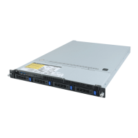
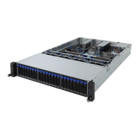
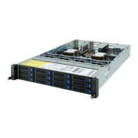
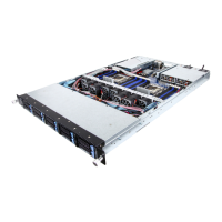
3-1 Front View
• Please Go to Chapter 3-3 Front Panel LED and Buttons for detail description of function LEDs.
No. Decription
1.
HDD bay#0
2. HDD bay#1
3. HDD bay#2
4. HDD bay#3
5. HDD bay#4
6. HDD bay#5
7. HDD bay#6
8. HDD bay#7
9. HDD bay#8
10. HDD bay#9
11. Front Panel LEDs and buttons
12 Front USB 3.0 ports
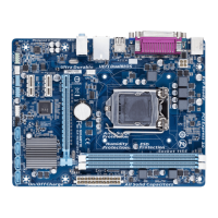
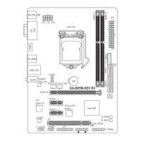
3-2 Rear View
No. Decription
1. Power supply fan
2. Power supply module cord socket
3. VGA port
4. RJ-45 LAN ports
5. ID switch button
6. RJ-45 COM port
7. USB 2.0 ports
8. 10/100/1000 Server management LAN port
9. USB 3.0 ports
10. Low-prole riser card bay
1
2 3 4 5 6 7 8 9
10
12
11
1
2
3
4
5
6
7
8
9
10
 Loading...