Do you have a question about the GJD D-TECT 2 IP and is the answer not in the manual?
Defines key programming parameters like Pulse Count, LED, and Relay outputs.
Explains how to enter and perform a walk test for detector alignment and function verification.
Explains the meaning of warning, caution, prohibition, and instruction symbols used in the manual.
Outlines critical safety advice regarding disassembly, handling, power supply, and environmental exposure.
Lists the default IP, subnet mask, and router settings for initial access.
Details how to access the web interface and set up a new username and password.
Guides on setting range, pulse count, and LED status via the web interface.
Covers TCP/IP settings, DNS, and port configurations for network integration.
Describes how to back up and restore detector configuration settings.
Explains the process for updating the detector's firmware to the latest version.
Details setting up alarm triggers based on PIR detection, delay, timeout, and light levels.
Guides on defining actions like triggering outputs or sending URL requests upon alarm events.
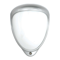
The GJD D-TECT 2 IP is an advanced outdoor motion detector designed for robust security applications. It leverages a sophisticated combination of PIR (Passive Infrared) detection and IP connectivity to provide reliable and intelligent intrusion detection. This device is highly configurable, allowing users to tailor its operation to specific environmental conditions and security requirements.
The core function of the D-TECT 2 IP is to detect human movement within its specified detection zones. It achieves this through multiple PIR beams, which are sensitive to changes in infrared energy, typically emitted by people. When a change in infrared energy is detected across multiple beams, the device processes this information to determine if an intrusion has occurred.
A key feature of this detector is its IP connectivity, which allows it to integrate seamlessly into modern network-based security systems. This means that alarm events, status updates, and configuration changes can all be managed remotely over a network. The device supports Power over Ethernet (PoE), simplifying installation by delivering both power and data through a single RJ45 cable.
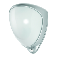
The D-TECT 2 IP incorporates a multi-beam detection pattern, designed to provide comprehensive coverage while minimizing false alarms. It utilizes both short, medium, and long-range beams, which can be adjusted and masked to create a precise detection area. This adaptability is crucial for outdoor environments where varying terrain, foliage, and potential sources of interference exist.
The device also includes two volt-free relay outputs, which can be used to trigger external alarm inputs on connected equipment. These outputs are magnetically immune and rated for a maximum of 24V AC/DC @ 50mA, making them suitable for a wide range of security system integrations. The contact operating timer for these outputs can be adjusted via the web-based user interface.
The D-TECT 2 IP offers extensive configuration options to optimize its performance in diverse outdoor settings. These settings can be accessed and modified through a user-friendly web-based interface, or for basic adjustments, via a programming button on the device itself.
The detection range is highly adjustable, with options from 8m to 30m. The device's lens module can be panned and tilted to fine-tune the coverage area. Furthermore, the detection pattern can be customized by masking off specific beams using self-adhesive silver masks. This allows installers to create precise detection zones, avoiding unwanted detection from areas like public pathways or moving foliage. For instance, masking the top section of the lens can reduce the range to 20m or even 6m, depending on the specific mask applied.
The pulse count setting determines how many times the unit must detect on both of its sensors before signaling an output. This feature helps to reduce false alarms caused by transient events like small animals or environmental disturbances. Users can select from different pulse count levels (1, 2, or 3) to suit their specific needs.
The device includes an LED indicator that can be configured to be either "Off" (disabled) or "On" (signals a detection). This is particularly useful during installation and walk tests for visual confirmation of detection.
A dedicated walk test mode simplifies the alignment and testing process. In this mode, the detection LED is automatically enabled, and the pulse count is set to 1, allowing for immediate visual feedback upon detection. The walk test mode can be activated via the programming button or the web interface and automatically ends after five minutes of inactivity, or can be manually cancelled. It is important to perform walk tests with the front cover in place to ensure the correct beam pattern is established.
The IP connectivity allows for comprehensive network configuration, including static IP address assignment or DHCP, subnet mask, default router, and DNS settings. HTTP and HTTPS server ports can also be configured. This ensures secure and reliable communication within the network.
The D-TECT 2 IP supports the creation of custom alarm events based on PIR detection. Users can define the event name, input (PIR detection), delay, timeout, and the specific action to be triggered. Actions include activating digital outputs (Output 1 or Output 2), connecting to a URL, or integrating with various GJD Visualiser and IP products, as well as Axis cameras. This flexibility allows for tailored responses to detected intrusions.
The device incorporates user management features, requiring a username and password for access to the web interface. A robust password policy ensures strong security, requiring at least 8 characters and a combination of small letters, capital letters, numbers, and special characters.
The firmware of the D-TECT 2 IP can be updated to add new functions or resolve software issues. This process is managed through the web interface, ensuring the device remains up-to-date with the latest features and security enhancements.
Configuration settings can be exported as a file for backup purposes or to easily copy settings to other units. This streamlines the deployment of multiple devices with similar configurations.
The D-TECT 2 IP is designed for reliable operation with minimal maintenance, but certain practices are recommended to ensure its longevity and optimal performance.
Periodically, the product should be cleaned and checked for safe use. This includes inspecting the lens for any obstructions or damage that might affect detection. If any problems are found, it is recommended to contact GJD or authorized partners for assistance.
The device is designed for outdoor use, but users should avoid touching unit connections with wet hands or when the product is wet from rain, as this could cause a short circuit or damage the unit.
During installation or servicing, the main unit should be held securely to prevent accidental drops or bumps against nearby objects. This helps to avoid physical damage to the device.
Users should never attempt to disassemble or repair the product themselves, as this could cause fire or damage to the device. All internal components are not user-serviceable, and any repairs should be handled by qualified personnel.
Only approved Power over Ethernet (PoE) power supplies should be used. Attempting to power the device with anything other than the RJ45 PoE connection can damage the unit.
By adhering to these usage and maintenance guidelines, users can ensure the D-TECT 2 IP provides effective and reliable security detection for many years.
| IP Rating | IP65 |
|---|---|
| Connectivity | Wired |
| Power Source | External power supply |
| Output Type | Relay |
| Operating Temperature | -20°C to +55°C |
| Ingress Protection | IP65 |
| Power Supply | 12V DC |
| Output | Relay N/O & N/C |
| Detection Technology | Dual Pyroelectric Infrared (PIR) and Microwave |
| Operating Voltage | 12V DC |
| Relay Rating | 1A at 24V DC |
| Material | Plastic |